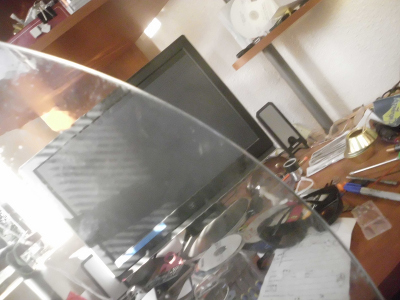
Goal: 30 inch [0.76m] diameter by 3/4 inch thick table top glass
Thickness: 0.75 inches
Comments: bought two 30 inch and three 42 inch (one broke in the kiln with a loud shattering bang) glass table tops. The glass I bought was not tempered. Never attempt to grind tempered glass - it will explode on you. However, tempered glass can be slumped and annealed in a kiln as the heating removes the tempering.
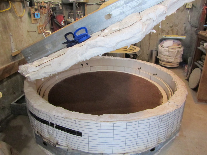
Goal: using a kiln, slump the mirrors to the proper curvature and anneal the glass
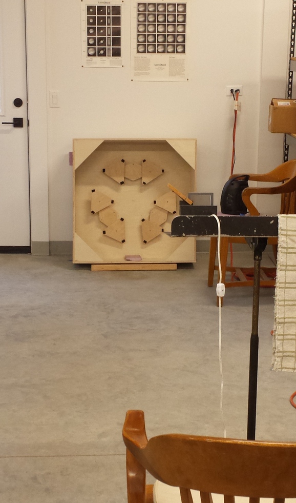
Process: Use precision refractory mold at David Davis with his homebuilt kiln. The more precise the mold, the less glass I need to grind. Mirror slumped face down over convex mold. Mold dimensions: 31.2" effective diameter (31 3/4" total dia), 11/16" sagitta, 89" focal length
Date: June-2014
Thickness: 0.75 inches
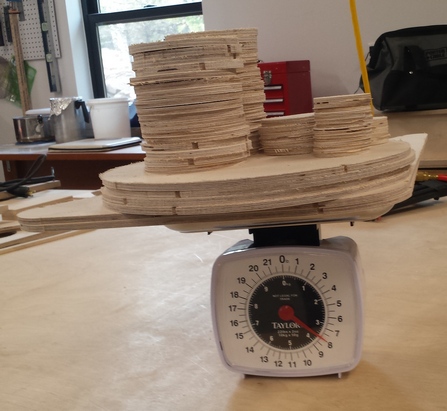
Weight: 43 pounds
Sagitta: 0.67 inches; focal length: 84 inches; F2.81
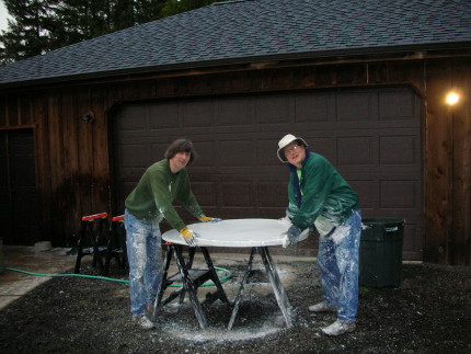
Comments: David Davis, a pioneer in large thin slumped meniscus mirrors, offered to slump large thin blanks for me using his homemade kiln. The point of slumping is to prevent the center from being ground through on large fast mirrors and eliminate the rough grinding stage. To slump the 30 inch [0.76m] and 42 inch [1.07m] glass blanks I need to make a refractory mold with a precision curve that the mirror will be slumped over.
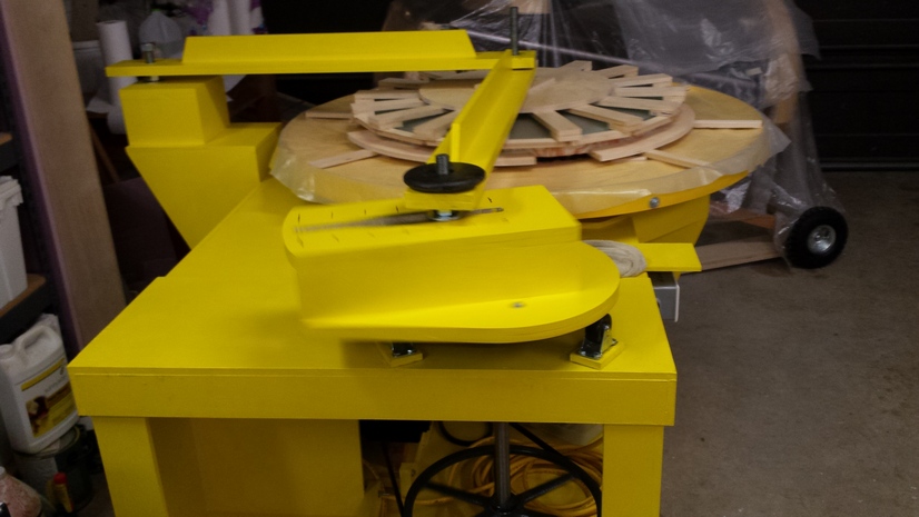
Here is David Davis' 72 inch kiln.
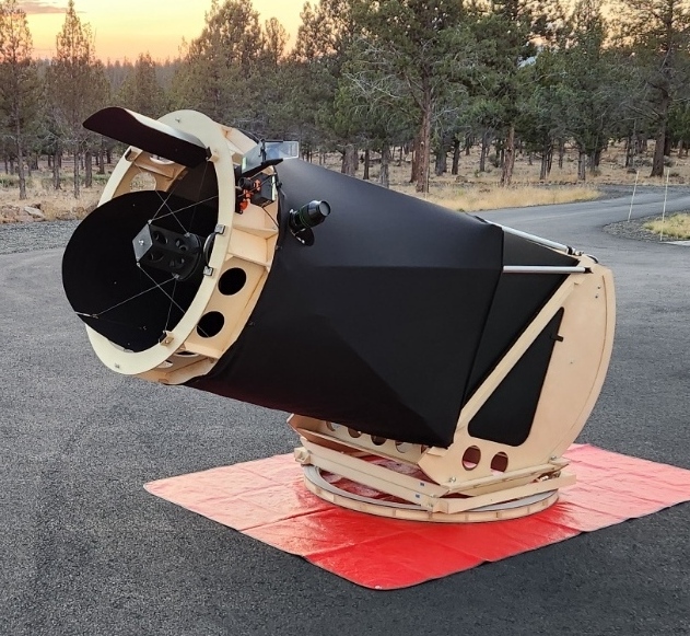
The 'mirror' is the reflective coating, a few nanometers thick. The metal coating must be held in position relative to itself across the mirror's face within a few dozen nanometers in order to sensibly perfectly focus the light. Glass takes a beautiful polish and can be shaped accurately to nanometers - arguably the most precise surface made by man or machine. Glass became the most common substrate after Karl August von Steinheil and Leon Foucault invented the silver on glass process in 1857. The glass substrate is supported by a 'mirror cell' which holds the glass and is in turn held in position by the 'optical tube assembly' (which also supports the focuser and diagonal), which in turn is aimed at the sky by the telescope's mount.
Glass bends at the nanometer scale - the thinner the glass the more it bends and shears. Thinner glass means lighter weight tube assemblies and faster cooling to match the dropping night time temperature. However, thinner glass is harder to support during polishing and calls for a carefully designed mirror cell that supports the mirrors. And you may have to change your mirror making process from one designed to work with stiffer full thickness mirrors to one that takes advantage of more flexible thinner glass. The flexibility of glass increases exponentially with diameter so larger glass needs to be proportionally thicker to retain the same stiffness.
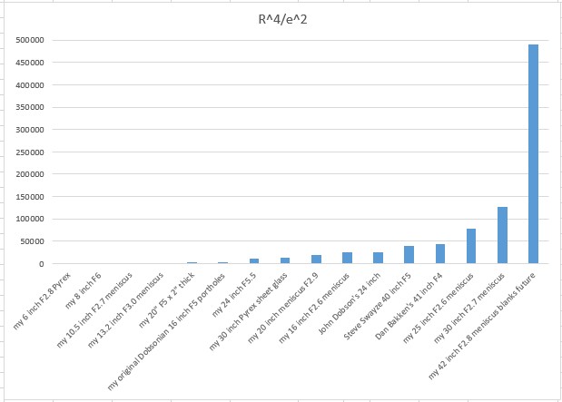
These 30 inch [0.76m] slumped to F2.8 mirrors are just under 3/4 inch [19mm] thick (finished thickness is 0.64 inches [16mm]). If we look at relative bending for the edge using the empirically derived formulation R^4/e^2 where 'R' is the radius and 'e' is the thickness, then we get the following values. All dimensions are in inches.
| description | diameter | thickness | R/e | R^4/e^2 | mirror cell design | edge support |
|---|---|---|---|---|---|---|
| my 6 inch F2.8 Pyrex | 6 | 1.00 | 6 | 81 | 3 pts | 2pt @90deg |
| my 8 inch F6 | 8 | 1.125 | 7 | 202 | 3 pts | 3 pt |
| my 10.5 inch F2.7 meniscus | 10.5 | 0.75 | 14 | 1351 | 3 pts | 2pt @90deg |
| my 13.2 inch F3.0 meniscus | 13.2 | 1 | 13 | 1897 | 3 pts | 2pt @90deg |
| my 20.5 inch x 2 inch thick F4.8 | 20.5 | 2 | 10 | 2760 | 9 pts | 2pt @90deg |
| my Dobsonian 16 inch F5 portholes | 16 | 1 | 16 | 4096 | carpet or 9 pts | sling |
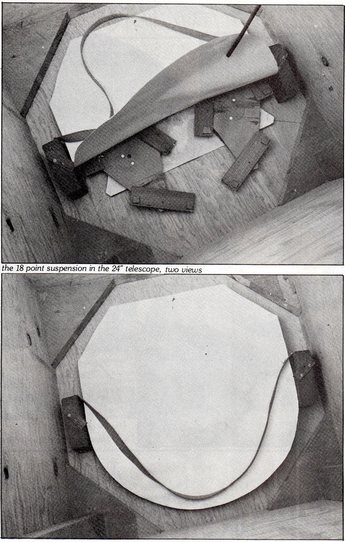
| my 24 inch F5.5 | 24 | 1.4 | 17 | 10580 | 18 pts | sling |
| my 30 inch F4 Pyrex sheet glass | 30 | 2 | 15 | 12656 | 18 pts | sling |
| my 16.25 inch F2.9 meniscus | 16.25 | 0.4 | 40 | 25600 | 6 pts | sling |
| John Dobson's 24 inch | 25.5 | 1 | 26 | 26427 | 18 pts | sling |
| Steve Swayze's 40 inch F5 | 40 | 2 | 20 | 40000 | 27 pts | sling |
| my 25 inch F2.6 meniscus | 25 | 0.56 | 44 | 77160 | 9 rings | 2pt @90deg |
| my 30 inch F2.7 meniscus | 30 | 0.63 | 48 | 127551 | 18 pts | sling or central hub |
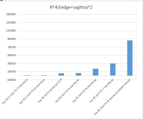
For meniscus mirrors if we take the 'total thickness', that is, the edge plus the sagitta, then we get the following table and chart. These values are similar in relationship to each other as above but are more modest in comparison to flat black mirrors. These values may be a better fit for what I am finding at the test stand and in the telescope.
| description | R/(edge+sag) | R^4/(edge+sag)^2 |
|---|---|---|
| my 10.5 inch F2.7 meniscus | 11 | 760 |
| my 13.2 inch F3.0 meniscus | 10 | 1123 |
| my 16.25 inch F2.6 meniscus | 20 | 6400 |
| my 25 inch F2.6 meniscus | 21 | 16954 |
| my 30 inch F2.7 meniscus | 23 | 29956 |
The 13.2 inch meniscus acts like standard flat-back mirrors (as does the 20.5 inch x 2 inch thick Pyrex mirror), but the 25 inch is definitely floppy: I saw that during fine grinding as the blank flexed and scratched at 9 micron aluminum oxide, necessitating a return to 25 micron AlO2. I can control the 25 inch mirror's edge nicely if I support it properly on the test stand; the mirror forms a beautifully round star test image at the eyepiece. So I feel buoyed for good chances for the 30 inch blanks. In comparison, the 42 inch blanks are intimidating.
Still, working with and developing processes for thin glass (less than an inch [25mm]) for many years feels normal for me. Thicker glass seems quite bloated and heavy and whatever ease of mirror cells they allow is eaten up by the complexity of fans moving air attempting to equilibrate the glass to the ever changing night air temperatures. And as a mirror maker I cannot emphasize enough how much I appreciate lifting lighter blanks countless times.
After completing the 30 inchers, I found the 30 inchers to be floppier than the 25 inch when tipped on edge for testing. The difficulty is not the thinness of the glass, or the glass type. Instead it is the supporting the mirror's edge. The column, 'R^4/e^2', which is the mirror radius to the 4th power divided by the thickness to the 2nd power, best describes the difficulty of supporting the mirror's edge.
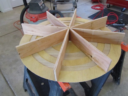
To make the precision refractory mold, I first had to make a plaster mold to pour the refractory material into; to make the plaster mold I had to make a second plaster mold to precision grind the plaster mold; to make these plaster molds I started with a wooden convex form.
The form is 31 inches wide to accommodate the 30 inch glass during slumping.
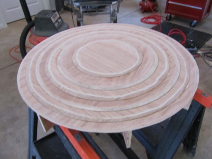
Making the concave plaster mold from the wooden mold
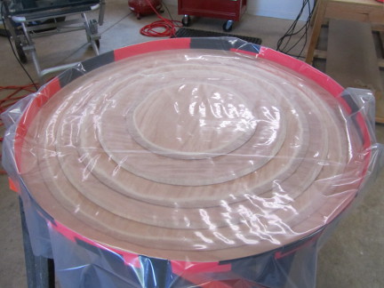
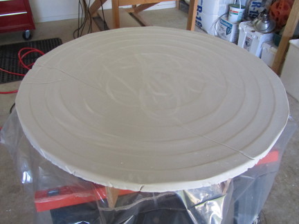
I simply cast a second plaster mold using the concave plaster mold as the master.
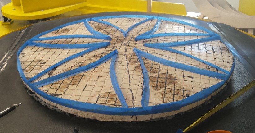
Pictured is Jerry Oltion and Mel Bartels grinding the 44 inch molds (suitable for 42 inch mirrors) using 60-90 grit.
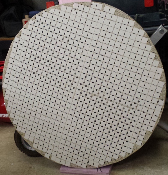
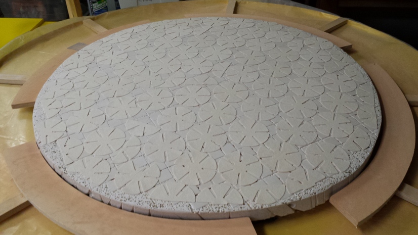
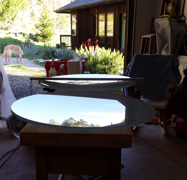
Here are the two 30 inch molds after grinding.
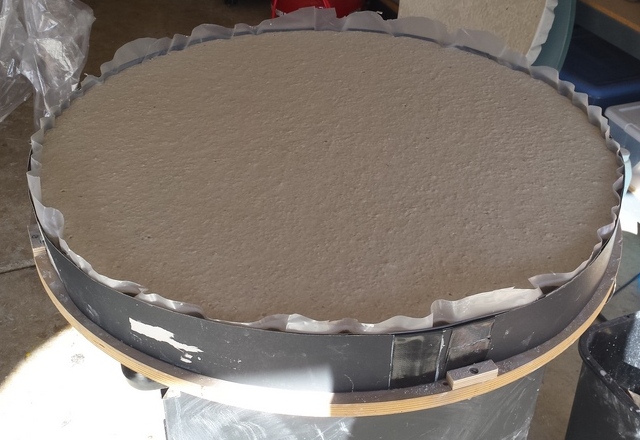
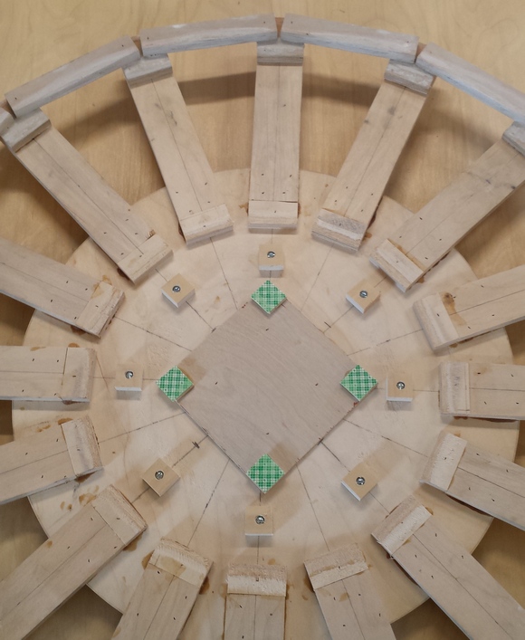
I made the convex refractory from the concave plaster mold
I also made a 44 inch refractory mold at the same time, pictured here with the 31 inch mold in front.
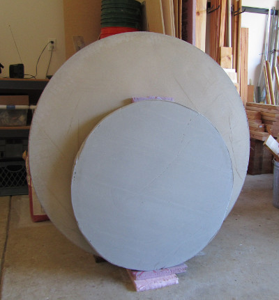
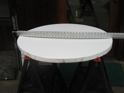
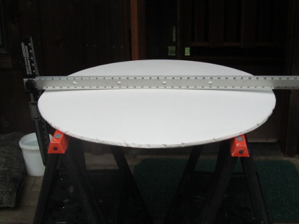
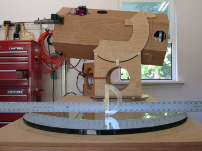
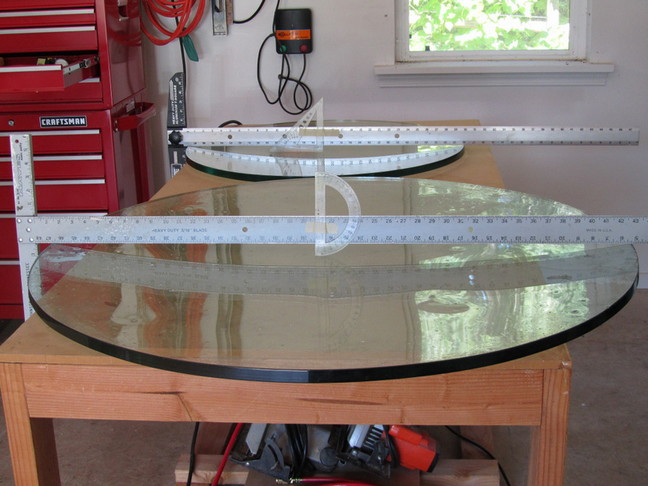
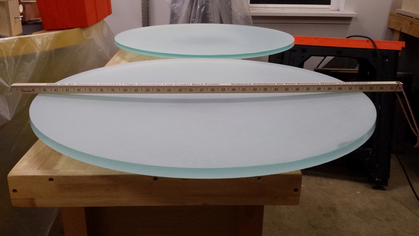
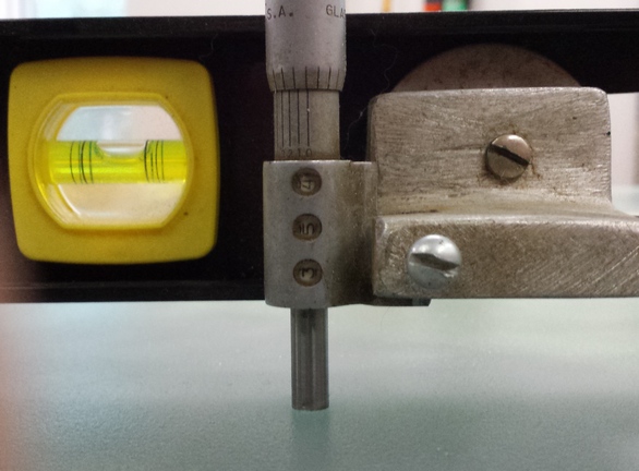
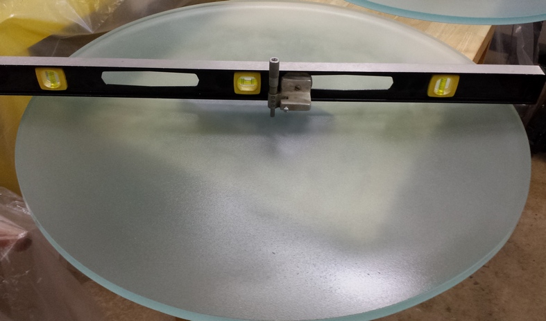
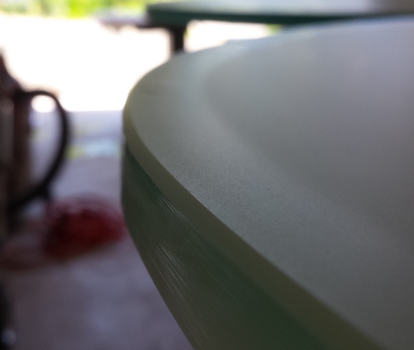
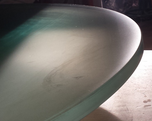
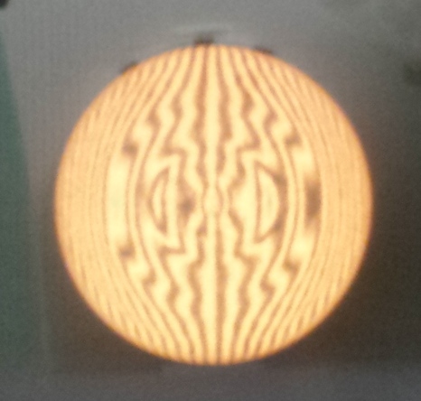
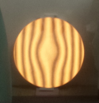
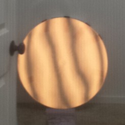
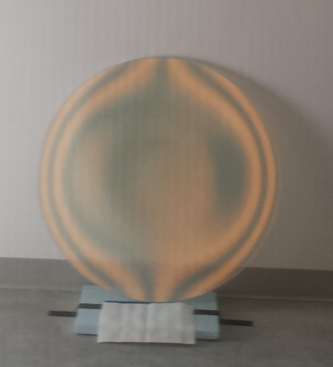
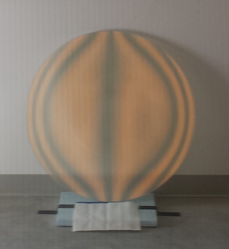
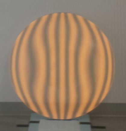
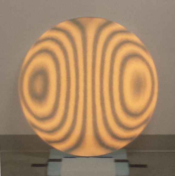
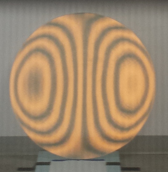
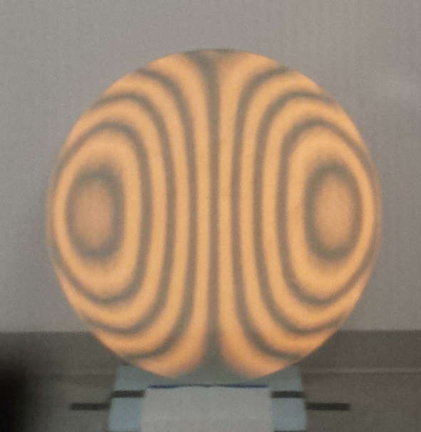
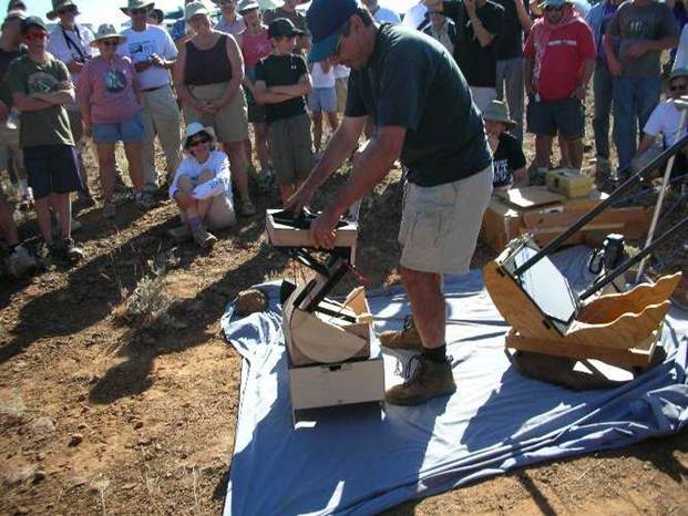
Pictured is one of the 30 inch slumped mirrors showing the sagitta of 0.7 inches [18mm] for F2.8 with a focal length of 84 inches [213cm].
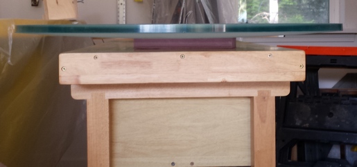
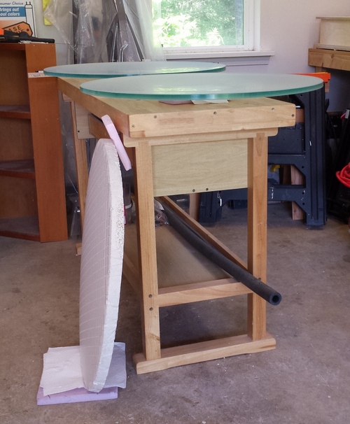
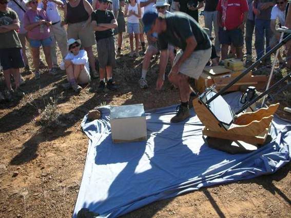
And here is one of the 42 inchers in front and a 30 incher in the back.
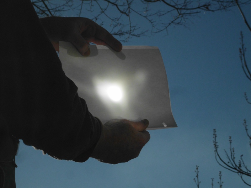
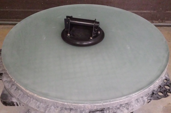
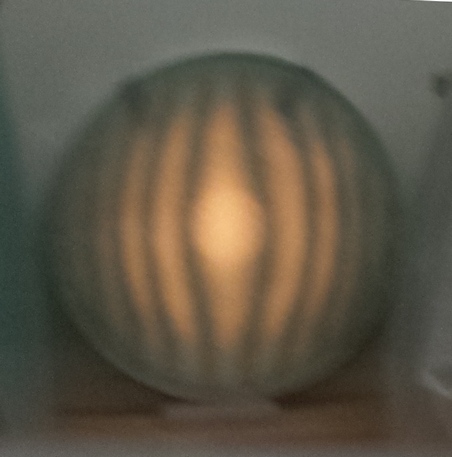
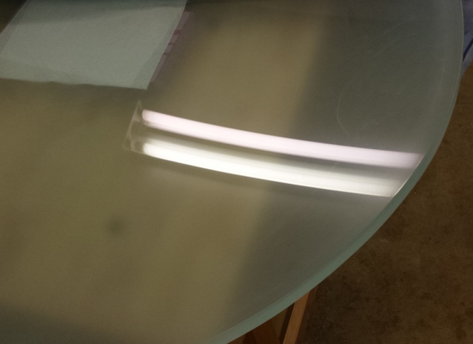
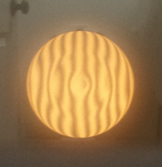
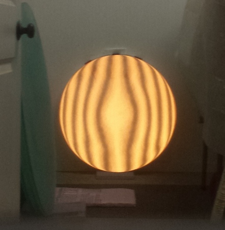
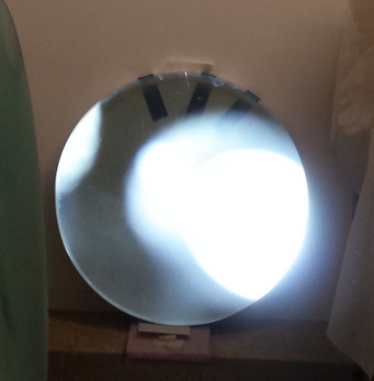
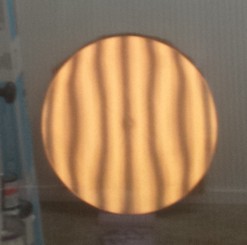
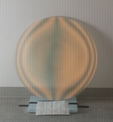
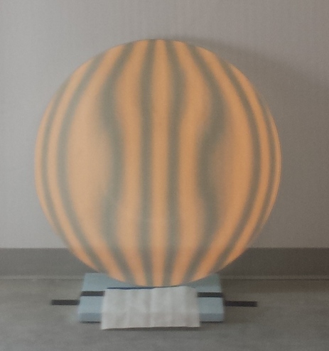
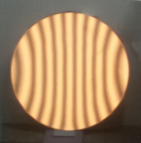
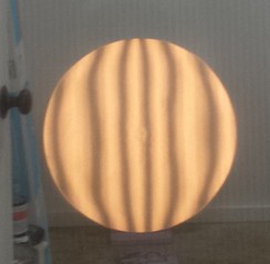
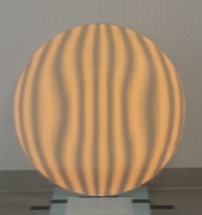
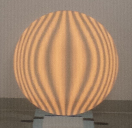
The slumped mirror focuses sunlight well.
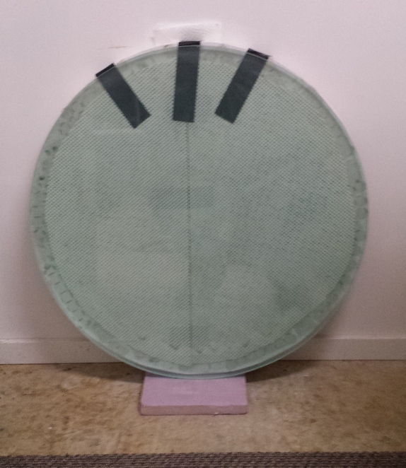
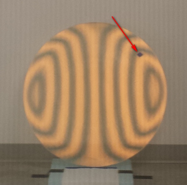
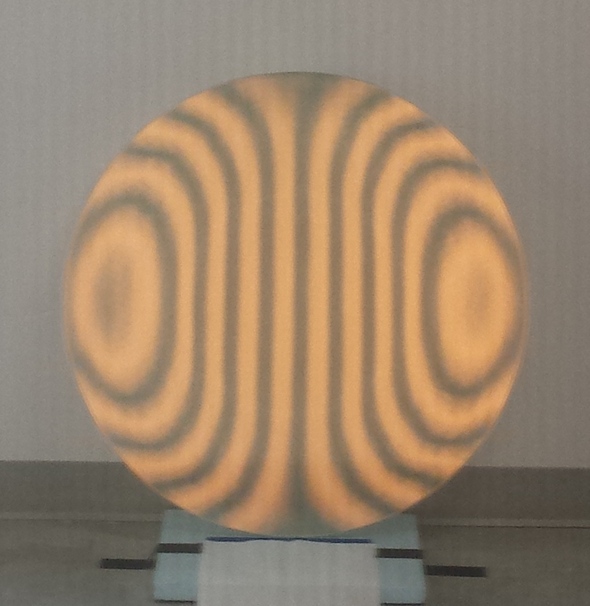
Testing the anneal by looking for strain using polarized light.
You can read more on my precision molds here.
Goal: create regular smooth curves on mirror backs and fronts; remove divits caused by air bubbles during slumping
Process: grind mirror faces against mirror backs using 1/3 W strokes by hand with 10 minute wets
Date: December-2018
Thickness: 0.69 inches, a reduction of 0.062 inches
Weight: weight reduced to 39 pounds [17.7kg] from 43 pounds [19.5kg]
Sagitta: 0.67 inches; focal length: 84 inches; F2.81
Comments: 1/16 inch glass removed. One low spot near edge on each black remains. When tapped, one blank rings quarter step higher than the other.
One low spot at the edge remains on both blanks. Blanks bevels front and back using diamond cloth against hard backing at 45 degree angle.
Goal: create two tools: one to grind the mirror faces in common against and the other to grind the mirror backs in common against.
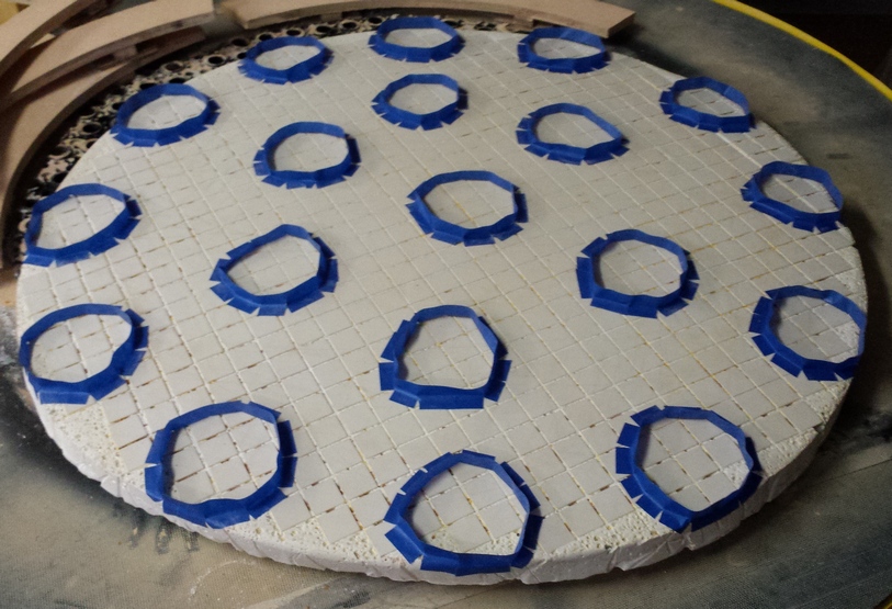
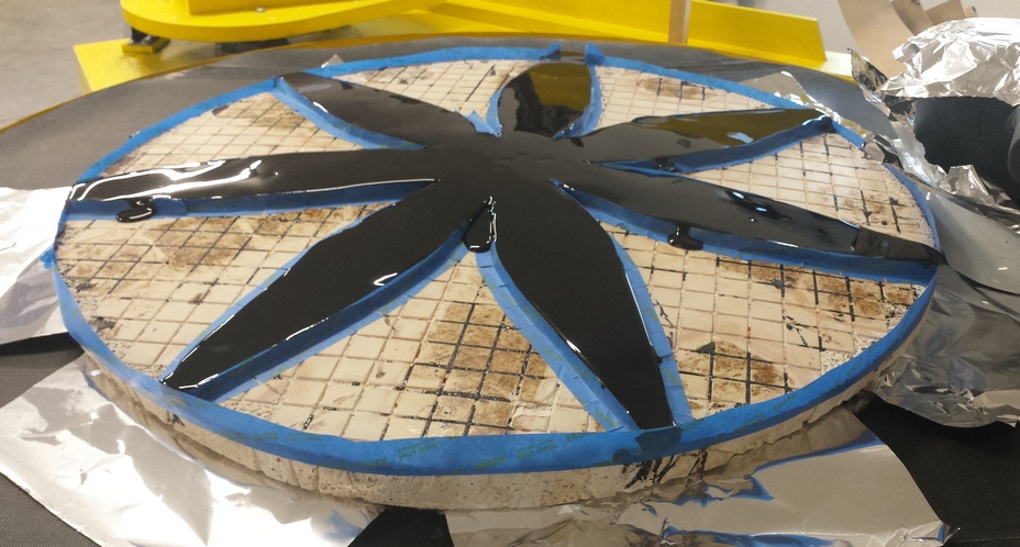
Process: cast frontside tool as below with mixture thicker and nearly a whole 5 gallon bucket's worth (4 gallons of mixed Hydrostone, water and vermiculite); edge thickness 1 1/4 inches
Date: January-2019
Comments: mixing in vermiculite reduces weight by up to half.
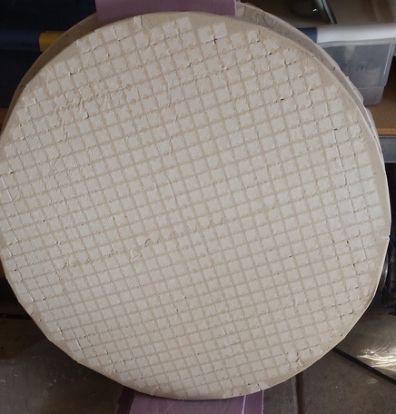
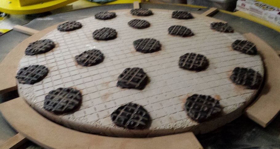
Full sized Hydrostone tools for large mirrors are very heavy. I determined to cut the weight by half by mixing in an equal volume of verimiculite. Here's an image of the convex mirror face grinding tool after pouring. And following is an image of the same tool with embedded tiles.
My tool making process:
The result is tiled tools that weigh less than the mirrors.
I will use one tool for both mirror backs and one tool for both mirror faces. Grinding proceeds faster with one tool for two mirrors. For example, the second mirror reaps the benefit of the first mirror shaping the tool.
Goal: grind mirror backsides to common curve, removing low areas
Process: alternate blanks on single tiled tool using 1/3 W to 1/2 W strokes with 10-15 minute wets of 60-90 carborundum grit
Date: January-2019
Comments: initially rough going; after 1 hr the outer 1/3 of the tool is in contact: center is low by 1/64 inch (60 grit is 1/100 inch size). Took a couple of hours for centers to come into contact for smooth grinding action.
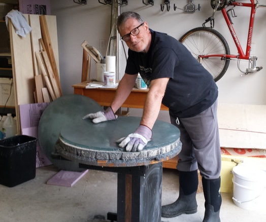
Mel grinding the back side of a 30 inch mirror over a full sized tiled tool; you can see the other 30 inch in the left background. Rough grinding is hard and messy.
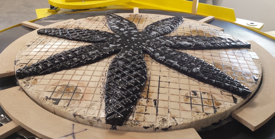
After rough grinding most of the tool is in contact with the mirrors though it is clear that some of the Hydrostone leaked under the tiles. I spent 3 hours apiece, total of 6 hours.
Goal: grind mirror frontsides to common curve, removing low areas and dimples
Process: alternate blanks on single tiled tool using 1/3 W to 1/2 W strokes with 10-15 minute wets of 60-90 carborundum grit
Date: January-2019
Thickness: 0.665 inches, a reduction of 0.033 inches
Weight: weight reduced to 38 pounds [17.2kg] from 39 pounds [17.7kg]
Sagitta: 0.656 inches; focal length 85.2 inches; F2.85
Comments: initially rough going; after 1 hr the outer 1/3 of the tool is in contact: center is low by 1/64 inch (60 grit is 1/100 inch size). Took a couple of hours for centers to come into contact for smooth grinding action. Had to bevel again.
After two hours apiece of alternating wets using 60-90 grit, the mirror faces are free of blemishes except for an edge dimple in each blank.
The sagitta of both mirrors exactly match and is now at 0.646 inches or F2.9.
After a few more hours of grinding, the edge dimples are gone. I also increased sagitta to my target of F2.8. Each mirror weighs 38 pounds [17kg] and is 0.665" [17mm] thick. The edge thickness and sagitta are nearly identical!
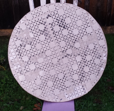
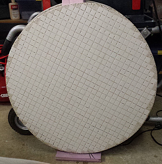
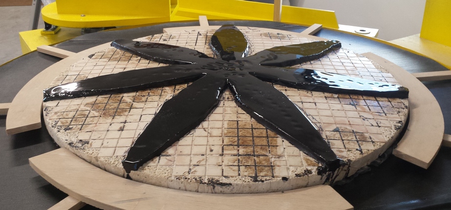
Here's what the convex tiled grinding tool looks like after completing rough grinding.
Goal: remove pits caused by rough grit; work towards F2.8
Process: alternate blanks on single tiled tool using 1/3 W to 1/2 W strokes with 15 minute wets of 220 carborundum grit
Date: February-2019
Comments: took a couple of hours for centers to come into contact for smooth grinding action. It is important to grind the back to a regular shape with no high or low spots. High spots mean that the glass is thicker and stiffer causing more polishing action resulting in local or high order astigmatism. It is also important to grind the back using small grit to minimize the Twyman Effect. The Twyman Effect occurs when the backside surface is coarse ground causing the front polished side to bend inward. The remedy is to fine grind if not polish the back side. Having arrived at the desired curves on the back and front sides, each side is ground in turn through the finer grits in order to gradually smooth both.
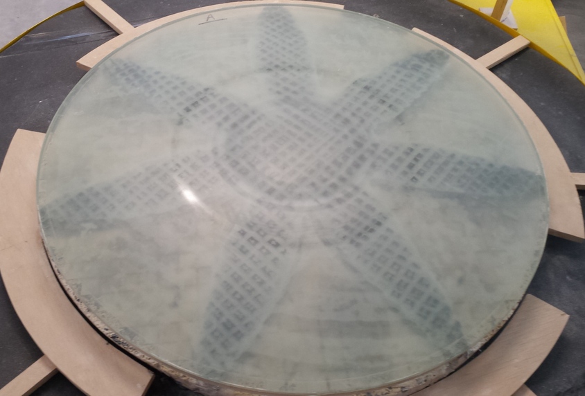
I am using a glass puller to push the glass back and forth. You can see that the tiles show through the dry back side nicely as the end of 220 grit grinding nears. This indicates that the mirror face is nearly done with 220 carbo grit and that the mirror face is spherical with good contact from center to edge.
Goal: remove pits caused by rough grit; work towards F2.8
Process: alternate blanks on single tiled tool using 1/3 W to 1/2 W strokes with 15 minute wets of 220 carborundum grit
Date: February-2019
Thickness: 0.65 inches, a reduction of 0.025 inches
Weight: 38 pounds [17.2kg]
Sagitta: 0.652 inches; focal length 85.7 inches; F2.87
Comments: took a couple of hours for centers to come into contact for smooth grinding action. Opened up a few channels between tiles using file. Edge dimples shrunk such that they are in the bevel. Use a drop of Dawn dishwashing detergent to prolong wetness.
I like to use a short series of grit sizes: each grit size is composed of a range of grit sizes, so a long series of grit sizes where the ranges overlap is not efficient. Also there is the clean-up between grits to consider. I use 220 carbo, 500 carbo followed by 20 micron AlO2. Smaller mirrors worked by hand can profit with a final step of 9 micron AlO2. Beveled again.
Mirror making on pause. For 10 days we were trapped without power and unable to drive down the private drive due to the worst snow storm in 50 years that left knee deep snow and many trees down.
Goal: grind with 500 grit to remove 220 pits
Process: alternate blanks on single tiled tool using 1/3 W to 1/2 W strokes with 15 minute wets of 500 carborundum grit later switching to 1/3 CoC (Center over Center) strokes
Date: March-2019
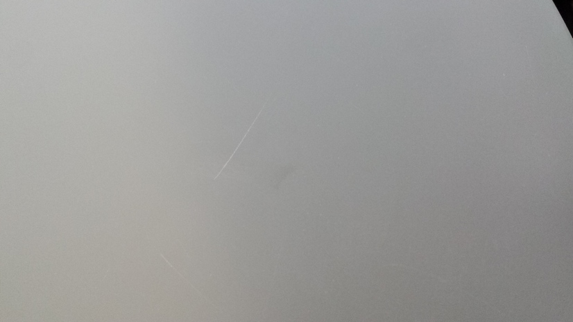
Comments: contact difficult at first: only edges in contact, but after an hour (1/2 per blank), contact smoother. No 220 pits casually visible after hour #3. Scratches appeared from hour #3 to hour #8: traced to loosening tiles.
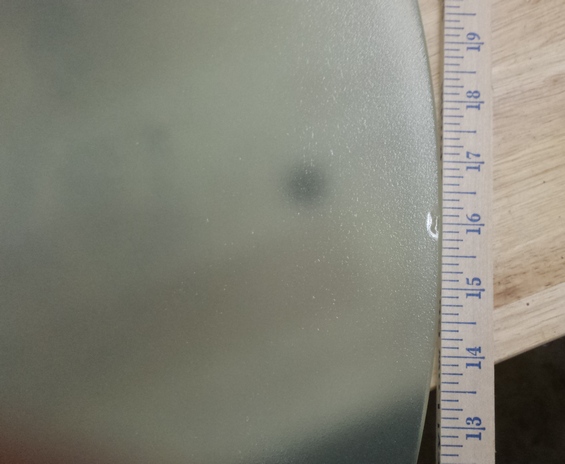
Here's what a scratch caused by a lose tile looks like. The scratch is about an inch long; mote the mirror's edge in the upper right corner.
Tiles popping off gave me a chance to measure their reduction in thickness. Tiles were ground down 0.05 inches while each glass face was ground down by 0.06 inches (60-90 grit: 0.033", 220 grit: 0.025" [compare to mirror thickness reduction of 0.062" when mirror faces were ground against mirror backs: the mirror faces and backs were both reduced by 0.031"]), so the tiles are 0.06*2/0.05=2.5x as hard as the glass. Grinding time per mirror was 5 hrs of 500 grit, 5 hrs of 220 grit and 4 hours of 60-90 grit; grinding times for the tool are double the individual mirror numbers.
Goal: make a replacement tool to finish grinding the mirror faces as the first tool failed.
Process: a second tool was cast from Hydrostone with verimiculite this time with the tile webbing embedded in the plaster. A 5 gallon bucket was filled with water, then Hydrostone power mixed in and finally verimiculite and more water, all power mixed. This was poured over the mirror with cardboard rim and 1 mil plastic covering and tiles webbing side up (away from mirror face).
Date: March-2019
Comments: this tool is heavier, weighing 68 pounds, and is 1 1/4 inches thick at the edge, 2 inches thick in the center.
Goal: grind to bring tiles into good contact with the mirror and remove earlier scratches.
Process: 15 minute wets with long wide strokes
Date: March-2019
Thickness: 0.64 inches, a reduction of 0.01 inches
Weight: 38 pounds [17.2kg]
Sagitta: 0.653 inches (increase of 0.001"); focal length 85.5 inches; F2.86
Comments: initial contact not bad for such a large tool and grit size; contact starting at edge. After 2 hours, 95% of the tiles are in contact.
Here's what the second tool looks like at this stage:
Goal: grind with 500 grit to remove 220 pits
Process: alternate blanks on single tiled tool using 1/3 W to 1/2 W strokes with 15 minute wets of 500 carborundum grit, later 1/4 CoC (Center over Center) elliptical strokes, then 1/3 CoC, finally offset arc'd strokes.
Date: March-2019
Thickness: 0.635 inches
Weight: 38 pounds [17.2kg]
Sagitta: 0.666 inches (increase of 0.013"); focal length 83.9 inches; F2.81 (17mm Ethos field=0.69deg, pupil=5.3mm, mag=144x)
Comments: before starting, freshened up the bevels with 15 minutes on each mirror, 8 times around with the diamond cloth. Good contact in first hour of grinding; no 'pinging' sounds like first tool; no scratches. Movement at the 4 hr mark is so smooth and even as I swap between blanks, an incredible joy.
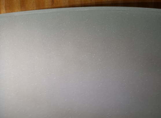
Pits remaining near the edge at the 3 hr per mirror (6 hr total) mark.
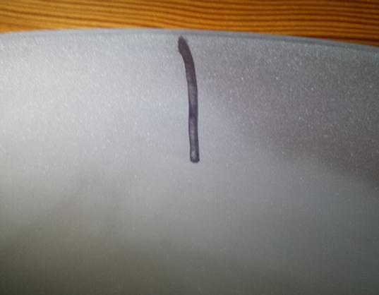
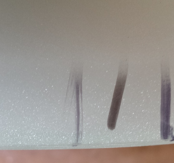
At the 5 hr (10 hrs total) per mirror mark, pits remain in the outer couple of inches. At the 10 hr (20 hrs total) mark, this outer zone is an inch wide and disappearing very slowly as the sagitta incrementally deepens. The mark is an inch long.
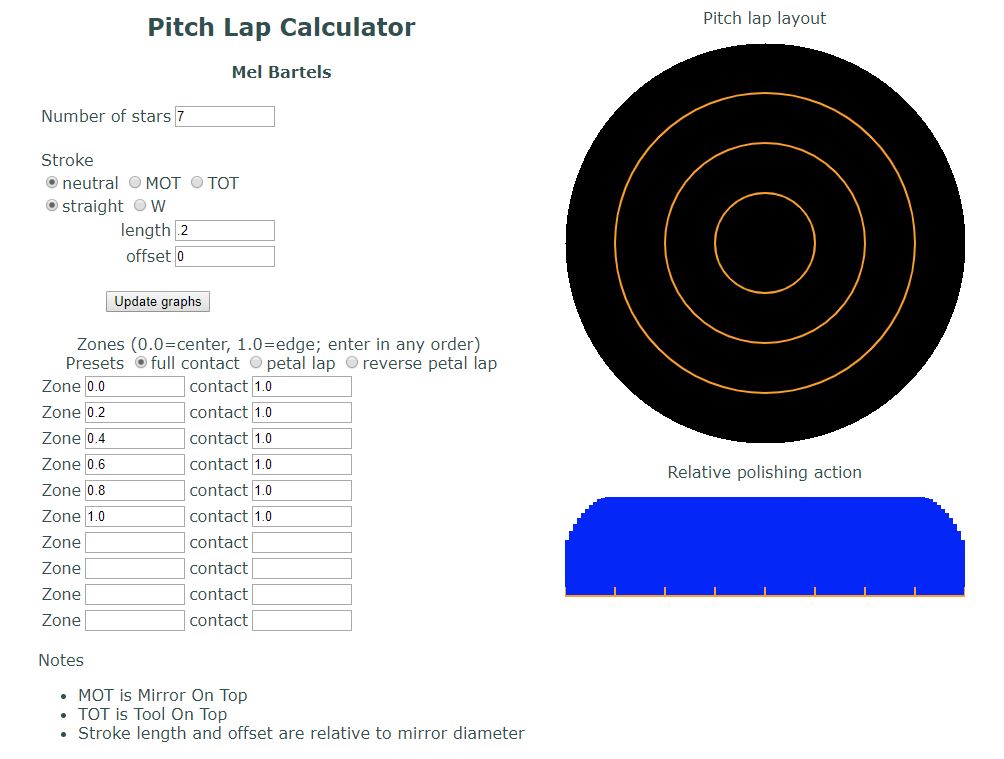
Subsequent grinding shows that the ink marks remain in the outermost half an inch. Normally 500 grit is a 2 hr operation, 4 hrs at most with a very large mirror; normally I'd flip the mirror over and work the tool on top accentuating effort at the edge, but here, I need to continue with mirrors on top of a heavy tool. Adapting my pitch lap calculator to illustrate relative grinding action at the edge, I see that the extreme edge gets maybe half the grinding action that the rest of the mirror receives. Changing stroke length does not substantially affect the grinding action at the extreme edge.
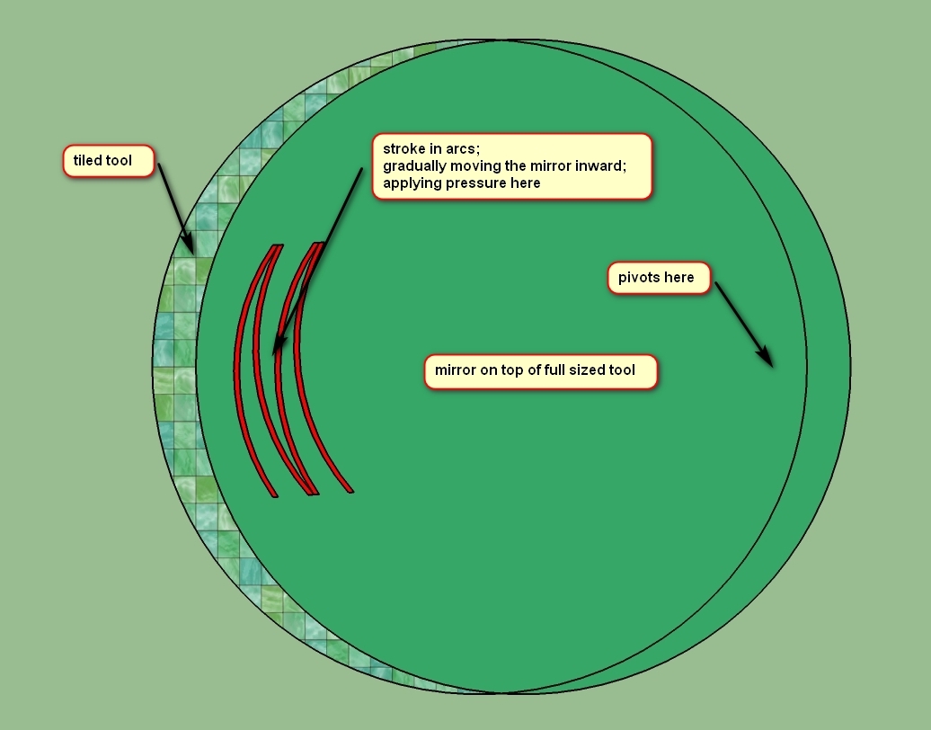
At the 37 hr mark (!), the outer 1/4 inch is still full of 220 pits and the sagitta has deepened. With these large mirrors on top, the edge is not getting much action. I need to simulate tool on top to work down the edge. I devised an accentuated pressure, offset arc stroke where the hands press with accentuated pressure near the edge. The mirror's edge is stroked in an arc of 1/3 mirror diameter with the mirror center moving about half that amount, resulting in the mirror's edge that overhangs on the other side to hardly move. The arcs are gradually moved inward in a 'W' action where the mirror's edge is arcing across the tool's center. After five hours with this stroke the extreme edge is receiving action though small pits remain in the outermost one-eight inch; the edge thickness is down to 0.635 inches but the sagitta is up to 0.668 inches; the mirror also slides across the tool slightly easier. After applying this new stroke, the sagitta shrunk slightly to 0.666 inches.
After 48 hrs the grinding became sticky, likely because the tiles had ground down in the center resulting in no depth between tiles especially in the center. One mirror still has some 220 pits at the extreme edge and there is a minor scratch in the other mirror near the edge. The mirror with pits at the extreme edge is also 0.005 inches thicker than the other mirror. I opened up the channels using a diamond cloth wrapped around a sharp edged file.
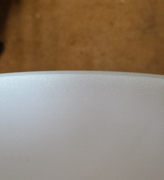
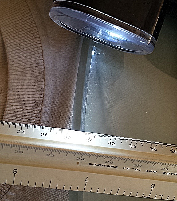
Here is the mirror's edge. I decided to go onto 20 micron grit, hoping to pick up the edge during the final smoothing.
Goal: finish off fine grinding using 20 micron aluminum oxide in preparation for polishing
Process: some CoC short strokes; mainly offset arc'd strokes
Date: April-2019
Thickness: 0.64 inches
Weight: 38 pounds [17.2kg]
Sagitta: 0.670 inches; focal length 83.4 inches; F2.79 ((17mm Ethos field=0.70deg, pupil=5.3mm, mag=143x)
Comments: aluminum oxide planes the glass leaving a smoother surface than does silicon carbide grit which digs into and fractures the glass to a depth three times the size of the grit. Using aluminum oxide dramatically cuts polishing time and increases the odds of a haze-free surface even when the aluminum oxide is 20 microns in average size and the previous stage's 500 size carborundum grit is 18 microns on average (all grit comes with a variance in size; higher quality grit having a tighter variance).
The initial hour was difficult as I apparently was using too much grit, plugging up the channels. During the second hour the mirrors began moving fingertip smoothly. The edge of the better mirror is nearly free of pits with the lagging mirror's edge sporting fewer pits.
After 4 hrs each mirror, 8 hrs combined, one mirror is finished with 20 micron AlO2 except for a couple of tiny white specked pits at the edge while the other blank still sports numerous 220 pits and smaller at the extreme edge. After 5 hrs each mirror, 10 hrs combined, the edge is cleaning up on one blank and the scratch is disappearing on the other blank. After 7.5 hrs each mirror, 15 hrs combined, one mirror's edge (0.7 inches wide) is low. I can feel the zonal discontinuity:
After cleaning all up and deepening the channels in the center of the tool to the same depth as the channels near the edge of the tool, one hour grinding (2 hrs combined) shrunk the recalcitrant zone from 0.7 inches to 0.1 inches wide. And at the 10 hrs per blank, 20 hrs total, the edge is pit free. The sharpie test passes if I combine short CoC strokes with my offset arc'd strokes.
Here's the finished edge:
and the mirrors and tool after finishing fine grinding (you can really see the deep curve):
Goal: polish out all pits and generate a regular figure.
Process: using my polishing machine, polish mirror on top of full sized tool covered with polishing pads.
Date: June-2019
Thickness: 0.64 inches
Weight: 38 pounds [17.2kg]
Clear aperture (now that bevels are set): 29.81 inches (3/16 inch less than 30 inches)
Focal length: 82.4 inches (measured to RoC of center zone with Ronchi tester); F2.76 (sagitta=0.674", 17mm Ethos field=0.71deg, pupil=5.4mm, mag=141x)
Comments: polishing is a chemical and mechanical process that makes the surface smooth (see my article on chemical mechanical polishing. While the chemical aspect of polishing can fill in pits in the glass surface, I like to polish for double the time to ensure that the glass is planed down below the bottom of pits left behind by fine grinding. This super polishing appears correlated with clean high contrast images at the eyepiece, even if this step merely acts to lower the chance that microscopic pits remain.
With mirror on top, face down, over the fine grinding tool covered in polishing pads and executing 1/5 long CoC machine strokes, the shine began in the center and dimly reached the edge after an hour polishing per mirror. Ronchigrams shows identically smooth very slightly parabolic figures with a flat edge. The test stand support consists of the plaster tool used to grind the back flat covered by no-stick kitchen mat. The plaster tool and the mirror rest on a piece of pink closed cell insulation. This is the stand that I developed for the 25 inch F2.6 half inch thick meniscus mirror. The stand is tipped back by 10 degrees so that the mirror is aimed a little above horizontal.
Potential sources of the astigmatism:
Initially the Ronchigrams of both mirrors show similar astigmatism which did not vary with mirror orientation. I discovered that adjusting the mirror back grinding tool and tipping it slightly more upward made the astigmatism go away. This was also the case with the 25 inch F2.6 mirror that exhibited non-rotating astigmatism until I adjusted its test stand.
It appears that my novel fine grinding stroke succeeded. Tentatively the mirrors pass a major milestone, namely that the mirrors show a regular figure that can be parabolized. One problem is that the polishing pads at the edge are not sticking well and being pushed off the tool resulting in the edge polishing very slowly.
I verified that the mirrors slowly rotate with respect to the tool.
A crude measurement of the RoC of the center zone came to 165 inches for a focal length of 82.5 inches and FR of 2.76.
Initial flash polish Ronchigram followed by an image of the pads on the tool and finally an image of the polishing machine in action.
Haze has retreated to the extreme edge after a few hours of pad polishing.
Larger mirrors polish more slowly than smaller mirrors. First, imagine an 8 inch being polished with a ten pound weight. For a 30 inch to polish as quickly we need 140 pounds of weight distributed evenly on the glass. And the force needed to push the glass or tool back and forth is 14x greater too. An 8 inch can easily need 20 pounds of force. The equivalent for a 30 inch is 280 pounds of force. That is a force that is humanly impossible and difficult for a machine too. So we accept slower polishing due to the lessened pressure. Secondly, the risk of scratching is greater with larger more flexible mirrors in the finest aluminum oxide finishing powders. For an 8 inch I fine grind through 3 micron aluminum oxide. For the 30 inchers, I stopped at 20 micron aluminum oxide. It takes more time to polish out the coarser haze. Thirdly, with MOT (Mirror On Top), the edge receives less polishing time. And finally in this project I am polishing two mirrors which doubles the time.
The 25 inch F2.6 mirror's edge also lagged badly, finishing after 17 hours of pad polishing. While serving as a guest expert at the Delmarva Mirror Making Workshop, I've learned to run the pads dry to speed up the polishing process. This seems to make a difference with the 30 inchers.
At the 20 hour per mirror mark, some of the pads near the edge are sliding off. Apparently the friction with the mirror exceeds the ability of the adhesive to hold the pad in place. Replaced all pads at the 48 hour mark.
At the 30 hour per mirror, 60 hours total mark, the edge haze is thinning out to a few pits and is hard to see with the unaided-eye. The Ronchi test shows no astigmatism and a fairly parabolized figure that likely will show stars at low power.
Here's the mirror on the test stand. The mirror rests on its edge on a piece of one inch thick closed cell pink insulation and rests against a rubber mat that is taped to the tool used to grind the mirror backsides. The tool leans backwards against the wall. The mirror stand is tipped back by 10 degrees. Simple but very effective for meniscus shaped mirrors.
At the 34 hour per mirror, 68 hour total, the center pads all came off. Apparently as before, they dried up such that friction against the glass was greater than the sticky material holding the pad to the tool so they began to slide up and over the other tiles. No immediately obvious damage seen. Guess I am letting the pads dry out too much in an effort to polish efficiently. I have been running 1.5 hours up to 2 hours before wetting pads again in an effort to run them as dry as possible. Will re-wet pads at 1/2 hour intervals. Failure occurs when one pad begins to slip, running into and crinkling the edge of another pad, which then fails. This cascades to a whole group of pads coming lose. After further thinking and inspection, I believe that the thin plastic cover that I throw over the tool is capturing moisture, wetting the pads too much that eventually cause the pad's edges to curve up and come lose.
Chattering also occasionally occurs which I trace to too fine of grade of cerium oxide.
Edge haze hard to see with the unaided-eye at the 40 hour a piece, 80 hours total mark. High power flashlight test and magnifying lens shows a few tiny pits remaining near the edge.
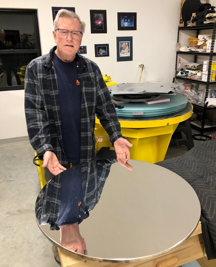
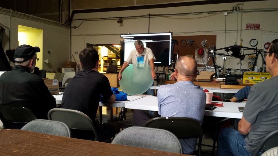
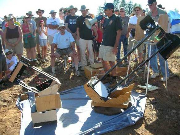
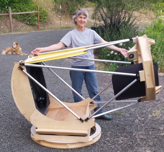
Here I am holding up one of the 30 inch nearly polished out blanks during my presentation at the 2019 Altaz Initiative conference in Portland, Oregon
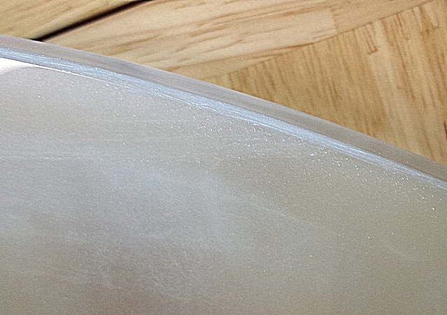
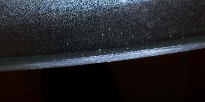
Here is the scatter test with an image using strong light at a flat angle to the glass, which exposes small pits at the extreme edge.
As the hours go by, I see that the parabolization increases to the point that the mirrors are over-corrected while the edge continues to polish slowly. The push-puller that moves the mirror back and forth across the tool is pressing too much on the mirror's center, flexing it downward and causing the mirror's center to preferentially be polished. Sanding the blocks that touch the mirror's back is transferring the polishing action more to the edge. On the plus side the mirrors have considerable parabolization now.
After an extraordinary amount of time, some very small pits remain at the extreme edge and the edge is hazy as seen in sunlight.
Considering that the mirrors have had edge issues since the 2nd tool was made, I've demonstrated to myself that this solid tool will not fully polish out the edge any time soon. I'll move onto pitch polishing, concentrating action to finish polishing the extreme edge, smooth out the figure and reduce the over-parabolization. Next time I'll use the grinding machine to spend the time to better matching the tool and mirror through the grit sizes.
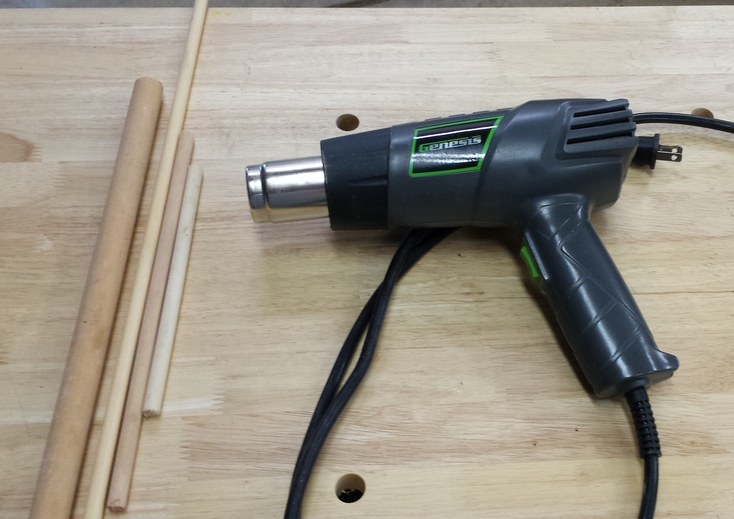
On another note, I did discover that heating the tool with a hot air gun made the pads stick ferociously.
Ronchigram showing the rough surface after pad polishing
Goal: generate a smooth figure ready to parabolize; polish out the pesky aluminum oxide pits that remain at the extreme edge
Process: using my polishing machine, polish mirror on top of full sized tool covered with pitch
Date: March-2020
Thickness: 0.64 inches
Weight: 38 pounds [17.2kg]
Clear aperture (now that bevels are set): 29.81 inches (3/16 inch less than 30 inches)
Focal length: 81.75 inches (measured to RoC of center zone with Ronchi tester); F2.74 (sagitta=0.679", 17mm Ethos field=0.71deg, pupil=5.4mm, mag=140x)
Comments: Prepped tiled Hydrostone tool with Burgundy pitch dissolved in paint thinner painted across surface. Poured pucks of Gugolz 55 onto the tiled tool and began polishing out the extreme edge and smoothing the curve. The pucks are 3-4 inches in diameter and 5/8 inch thick. Some haze appears about 1.5 inches in from the edge and haze seen by the eye with the proper illumination is visible about 1/4 inch inward of the edge.
Making the pitch pucks
After a few hours the edge is improving: the haze is mainly in the outermost 1/2 inch and the haze visible with a flashlight is in the outer 1/8 to 1/4 inch. The turned edge that the Ronchi test shows is shrinking in concert.
After more hours the magnifying lens with good lighting that still shows some tiny white specks at the extreme edge. Also the mirror's profile, while much improved, needs more smoothing.
I altered the lap into a spider shape with extra contact near the edge to smooth out the curve and continue working the extreme edge; I also reduced the downward pressure that the articulated pusher's edge exerts. This is making an immediate difference: the curve is smoother and the turned edge that carried over from pad polishing is going away. Luckily, both mirrors show exactly the same figure. Note the 42 inch F2.8 3/4 inch thick curved meniscus blanks leaned against the left hand wall waiting their turn.
Priority of work:
I discovered something remarkable: the Ronchi tester's astigmatism which I've seen for years varies based on which eye (I wear glasses) I use. I do not need to wear glasses while looking through the Ronchi grating so I am removing them from now on.
The turned edge is almost gone now. The lap has flattened out to 30.5 inches wide, greater than the mirror diameter. This modest over-sized lap makes for a good figure to the bevel.
Each mirror has gotten a scratch coming in from the edge. The scratches eventually polished out during figuring. Here is the flashlight test at RoC that I use to test for scratches. Look at 12:00 for the scratch that slants down towards 5:00. This batch of pitch is breaking apart into tiny brittle black specks. To combat this I am scrubbing the lap and thickening the polishing compound. Adding 10 pounds of weights to the pin pushing the mirror back and forth is causing the mirror to dig into the pitch more with progress at the edge. In retrospect countless hours have been wasted with these giant mirrors gliding over the lap due to lack of sufficient downward force and too thin and soapy of a mixture.
The feel through my fingers of freshly polished glass is wonderful: hard to describe. And the glass feels warm, even hot, across the entire surface immediately after pulling the mirror off the lap.
Polishing is thought to be a mechanical chemical process. Something to think about is the so called Beilby layer.
I polished away the scratch on the 'B' mirror and microscopic pits next to the bevel are hard to find.
Goal: generate smooth roughly parabolized surface
Process: using my polishing machine, polish mirror on top of full sized tool with a petal lap pattern
Date: August-2020
Thickness: 0.64 inches
Weight: 38 pounds [17.2kg]
Clear aperture: 29.81 inches (3/16 inch less than 30 inches: the blanks are 1/16 inch less than 30 inches diameter, the bevel is 1/16 inch wide)
Focal length: 81.5 inches (measured to RoC of center zone with Ronchi tester); F2.73 (sagitta=0.681", 21mm Ethos field=0.87deg, pupil=6.7mm, mag=113x)
Comments:
Retrospective so far:
Starting with a smooth spherical curve, my process increases parabolization while striving to keep the mirror's curve as smooth as possible. Adjustments to return the mirror to a smooth state are made while increasing parabolization. My technique is mirror on top of a full sized lap: the lap supports the mirror. This precludes low order or broad astigmatism. I use a petal lap to control polishing action across zones and vary the stroke length to blend zones. Mirror on top also controls scratching from contaminants that swirl around ordinary shops. My work with large thin fast meniscus mirrors is not only about parabolizing such flexible glass and developing mirror cells to support them but also about developing a good parabolizing process.
A zone is a radial area of a mirror that the polishing process tends to produce the desired result. Polishing a 4 inch [10cm] mirror to a sphere is very doable given a good process (good contact, pitch stiffness, appropriate strokes, and so forth). A 12 inch [30cm] mirror though acts like it has two zones. The parabolizing process must now incorporate the ability to adjust the inner and outer zones to achieve the desired paraboloidal surface. A 16 inch [40cm] acts like there are 3-4 zones. Faster mirrors have more zones than slower mirrors. Zones are also radial areas that have small amounts of deviation from a sphere when comparing their inside to their outside edges. A 4 inch F8 mirror needs 0.3 waves correction (all measured tangent from center or edge), a 8 inch F7 needs 1 wave, a 16 inch F5 needs 5.7 waves and a 30 inch F2.7 needs close to 65 waves correction. The zonal width also shrinks with increasing correction needed to parabolize. We can predict that a zone will polish consistently if the correction across the zone is a wave or less.
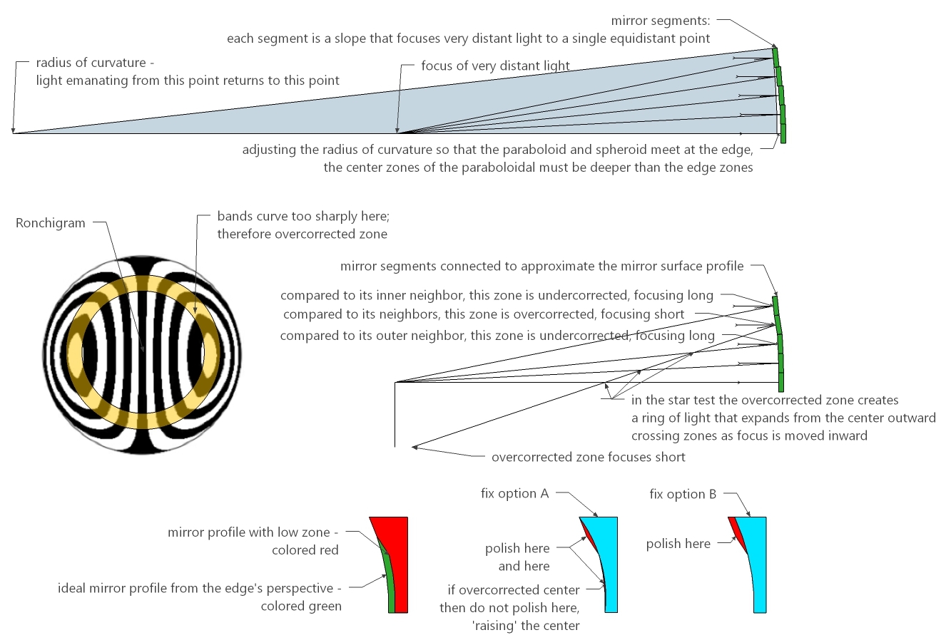
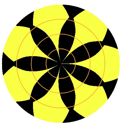
The mirror's surface is curved with varying slopes that direct the parallel light from afar to a point of focus. Tests like the Foucault and Ronchi are slope tests: they measure slope. Tests like the Bath Interferometer measure Optical Path Difference to derive the mirror's surface profile. Slopes can be calculated from the mirror's surface profile. While slopes can be strung together to calculate the mirror profile, they are not the mirror's surface. Thinking in slopes and testing directly with slopes is very useful when considering how to bring light together to form a nice tight star image or a nice sharp planetary image (as long as we understand that the tightly focused light forms an Airy Disk with rings due to diffraction - our goal is to form a perfect Airy Disk and rings). Here is how I think about slopes and deal with, in this case, a low 70% zone.
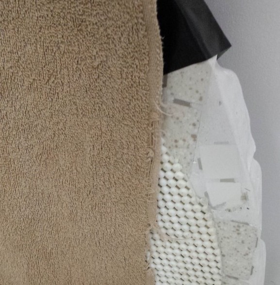
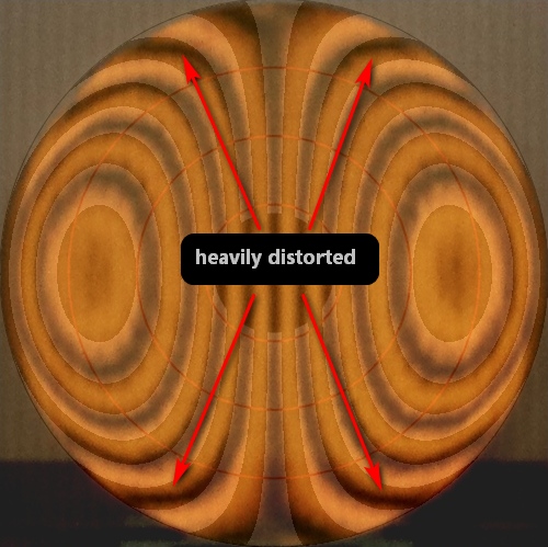
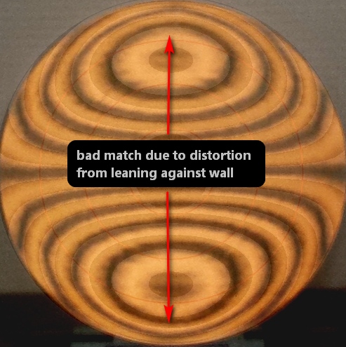
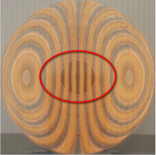
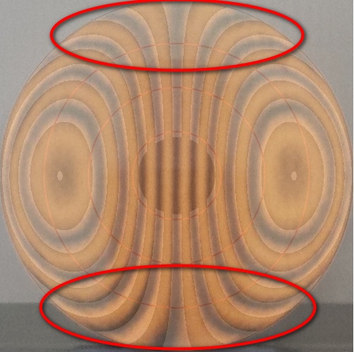
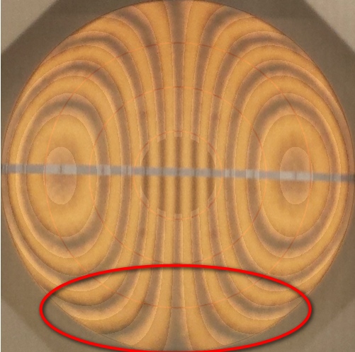
The above image is taken with the mirror propped against the wall sitting on a piece of hard pink insulation. Note the absence of heavy distortion next to the resting point on the insulation. I consider this a testament to the meniscus shape that strengthens the mirror in its entirety. Compare to the mirror resting on the tool used to grind the back side with a non slip kitchen mat and an old towel as a buffer, then the mirror resting on the grinding tool with only the non slip kitchen mat. The former shows some deformation at the mirror's bottom but the latter shows heavy wild distortion. The mirror is tipped back about 12 degrees in all instances. Is the tool warped? Unlikely because the Hydrostone is dimensionally stable. Does the non slip kitchen mat vary that much in thickness? I cannot see any variance. Clearly the simplest setup of propping the mirror up against the wall with a mild compressed bottom support is best. Interestingly, I can create bad deformations in the mirror by twisting the pink insulation piece. It has a bit of a groove in it now after placing the mirror on it so many times. If I align the groove parallel with the wall then the mirror distortions disappear.
More critically, I saw some bending on the test stand with the 25 inch F2.6 mirror.
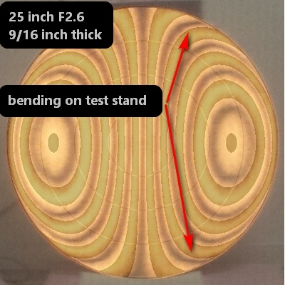
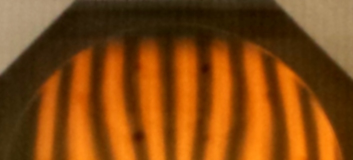
The 30 inchers bend much more: the Matching Ronchi says several waves.
Now compare to a Ronchigram taken with the tester rotated sideways. Wow, what a difference. At least the straight horizontal band suggests that there is no astigmatism.
Here are three Ronchigrams, the first supported from a single point against the mirror's back center and the second supported from a single point against the mirror's back side between the center and the edge. The third is with the mirror in a 18 point back flotation cell with a single bottom rigid foam edge support. The first two Ronchigrams are too distorted for careful analysis. I ignore the bottom of the mirror when supported by a single edge support.
Here is the mirror box and cell built for the star test rig that doubles as the test stand and a picture of my testing setup.

I notice during mirror cool down from a polishing session that the mirror sometimes undergoes subtle glass-quakes, where the radius of curvature and overall correction change subtly after a sudden quiver in the glass. Makes me wonder if the mirror should be re-seated in its cell during nightly observing as it cools.
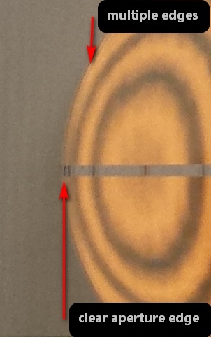
When the bright ring at the edge disappears then I know that the edge is good. Here's the ring, indicating a narrow TDE yet to be removed.
Here is a good lap configuration for keeping the edge 'up' or for fixing a turned edge. This can also return a mirror to quasi-spherical with a spider lap.
The mirrors' face gets hot to the touch during polishing, particularly towards the center of the mirror. Consequently the mirror's radius of curvature lengthens due to the expansion of the mirror faces. Here is the figure change after 5 minutes, 10 minutes, 15 minutes and one hour. Ignore the astigmatism - it is in the tester.
Here is the hot air gun and a series of wooden dowels that I use to re-press the channels when the pitch lap flattens too much along with the highly curved lap.
Here is the starting Ronchigram taken inside of RoC showing a clean edge that focuses short or rolled up (the opposite of a paraboloidal surface). This is due to the emphasis on removing microscopic pits at the extreme edge during the previous step.
I am beginning figuring with my standard Mirror-on-Top, one-third long center over center strokes using the machine. After a few hours, I have this:
Continuing with initial parabolization (a long ways to go yet), both mirrors look identical in figure and radius of curvature, with smooth curves. The lagging center and leading 75% zone is an echo of the polishing pressure to eliminate micro-pits at the extreme edge and to polish out the scratch at the edge of mirror B.
Quick progress: after a few short sessions:
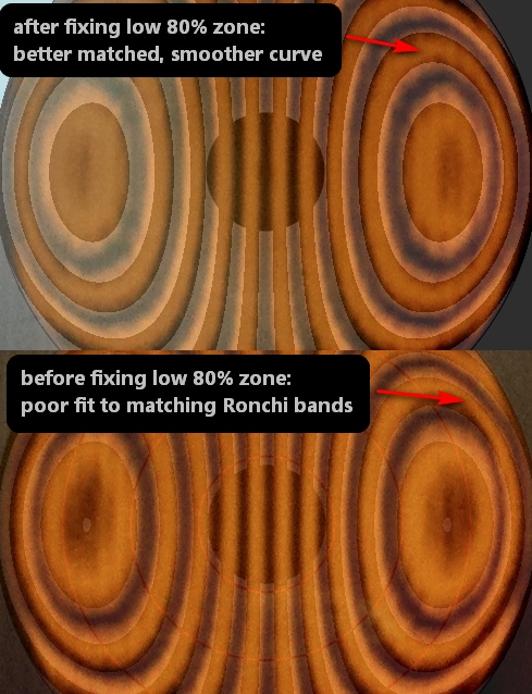
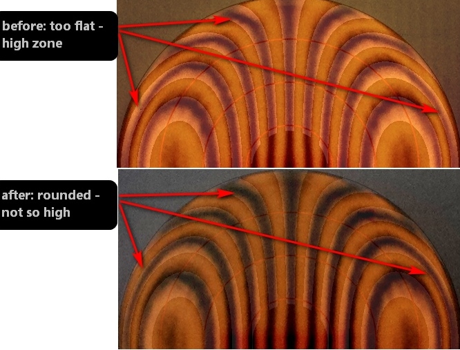
After deepening the center a fair amount and seeing to it that the curve is smooth, it is time to begin checking the mirror from beyond the radius of curvature. This brings out issues near the edge. Invariably with large fast mirrors there will be a kink which needs to be fixed. In the first image I marked the kink at the 80% zone with a piece of masking tape in the upper right. I address kinks right away for two reasons: I always strive to maintain a smooth curve as I nestle into full parabolization (fixing a kink or low zone can be quite time consuming after full parabolization is reached) and to demonstrate to myself that I have control of the paraboloidal generation process. I smooth out the Ronchi bands by decreasing polishing action where the mirror is kinked. I accomplish this by rolling a soapy wooden dowel across the pitch at the 80% zone, flattening the pitch's waffle pattern thereby lessening pitch contact with the glass. Very short one-sixth strokes smooth the narrow 80% zone in conjunction with the pitch pressed down out of contact and long one-third strokes smooth the overall curve. To deepen the center I use an extreme spider lap where the legs are very narrow with one-fourth long center over center strokes. Accentuated pressure near the mirror's edge as the mirror is brought back across the pitch lap by the machine also helps smooth the edge.
Rough parabolizing took about three dozen hours per mirror (I suppose one could say, a little less than an hour per inch of aperture), ranging from 15 minutes to 2 hours in length. Both mirrors received the same treatment each session. Reaching a quarter wave paraboloidal surface took about 45 hours per mirror.
After having trouble with the center continually flattening, I hypothesized that the pusher tool is deflecting the glass at its contact points that are centered near the 50% zone. The zone is being overpolished, making the center look flat. So I moved the contact points to near the center then polished for a 20 minute session. This deepened the extreme center. Then I moved the contact points outward a bit near the 30 percent zone. After another session I achieved smooth curves. This is a powerful technique to smooth the curve of the mirror. Also pictured is the underneath of the push showing the various touch points.
Date: September-2020
Lessons learned:
Goal: create smooth and accurate parabolized surfaces
Process: using my polishing machine, polish mirror on top of full sized tool varying the stroke and pitch contact as needed
Date: September-2020
Thickness: 0.64 inches
Weight: 38 pounds [17.2kg]
Clear aperture: 29.81 inches (3/16 inch less than 30 inches: the blanks are 1/16 inch less than 30 inches diameter, the bevel is 1/16 inch wide)
Focal length: 81.25 inches (measured to RoC of center zone with Ronchi tester); F2.73 (sagitta=0.684", 21mm Ethos field=0.88deg, pupil=6.7mm, mag=113x)
Comments:
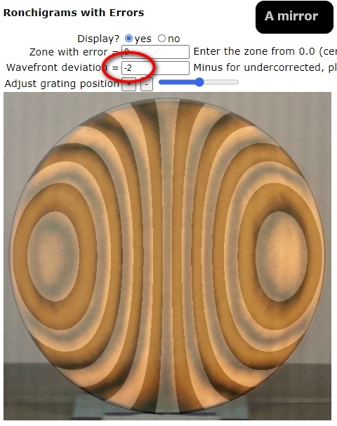
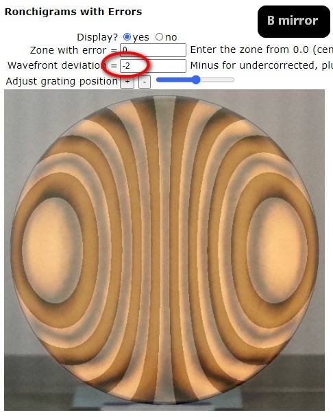
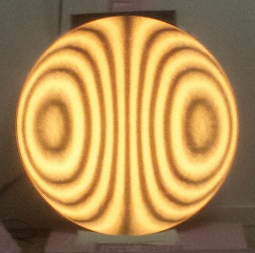
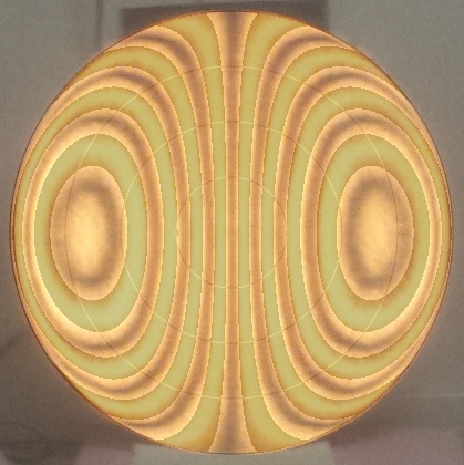
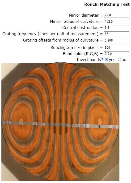
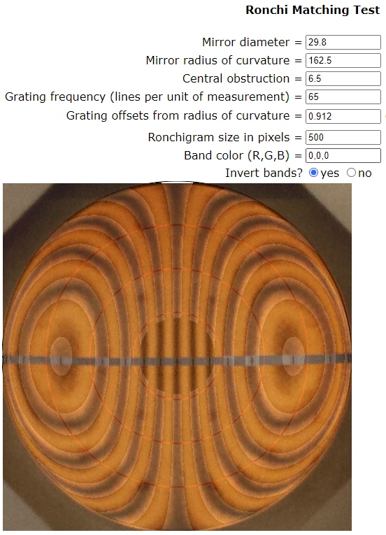
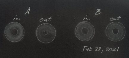
I do my first Matching Ronchi test while under parabolized so that I have time during subsequent parabolizing to adjust the curve proportionally. The more highly curved the bands due to the larger and faster the mirror, the sooner I begin matching Ronchigrams. The exact amount of undercorrection is immaterial; just so I am not overcorrected as this is difficult for me to repair. The first Matching Ronchi test shows that both mirrors are roughly two waves undercorrected with reasonably proportioned paraboloids. These mirrors require 65.3 waves of correction measured tangent to center or edge, or 16.3 waves correction for minimum parabolic deviation from sphere. The 'A' mirror is on the left and the 'B' mirror is on the right. The curves are not perfectly smooth, so in addition to deepening them, I will work to smooth them.
By the way, I compared my Matching Ronchi to a Zygo Interferometer on a commercially manufactured 12 inch [30cm] F5 mirror. My Matching Ronchi with Errors showed an undercorrected 0.6 wave error at best fit. Afterwards a professional optician friend used his Zygo at work and found an undercorrection of 0.6 waves, an agreement to 1/10 wave. For more on the Matching Ronchi test, go to ../ronchi.html.
By the way, as a reference, here's the final Ronchigram of my 25 inch F2.6 mirror, showing how smoothly the bands curve. The mirror's bands fit within the computer generated bands when overlayed and matched to each other.
The 25 inch focuses stars nicely with the star test at high power revealing a slightly low 85% zone. You can see that in the Matching Ronchigram: the bands are slightly too curved at the 85% radius from center. The mirror is close to one-sixth wavefront judging from the error matching section of my Matching Ronchi test as well as subjectively comparing the star test to other rated mirrors.
I seem to constantly battle a low zone near the edge. This happened on the 25 inch mirror and occurred earlier on the 30 inchers. How does lowering the center of a mirror cause a low zone near the edge? This happens a lot with my large fast mirrors. It is impossible to perfectly lower all zones at once in these mirrors. Indeed, other parabolizing techniques explicitly call for putting in the parabolization starting either at the edge moving inward or from the center moving outward. The classic 'W' parabolizing stroke for smaller slower mirrors does both at once: works down the center and the edge at the same time.
Let's start with a spherical mirror. Then let's perform a thought experiment by deepening the center more than the edge. The new 'best fit' radius of curvature encompasses the lowered center. But imagine what it does to the mirror's edge zone: it looks turned down! Yet we didn't touch the edge. In general we can say that lowering the center will cause zones near the edge to appear low.
I raised the low 80% zone by polishing the glass everywhere but on the low zone by depressing the pitch so that there is no contact on the low zone then using very short strokes:
Also, accentuated pressure applied a few inches inside the edge as the glass is brought back across the lap smooths the edge and removes zones.
If you are confident that the mirror is symmetrical, that is, has no astigmatism, then taking readings across the mirror's center from edge to edge is a smart way to figure a mirror. For example, think of the Foucault or the Poor Man's Caustic or the SLIT test.
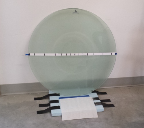
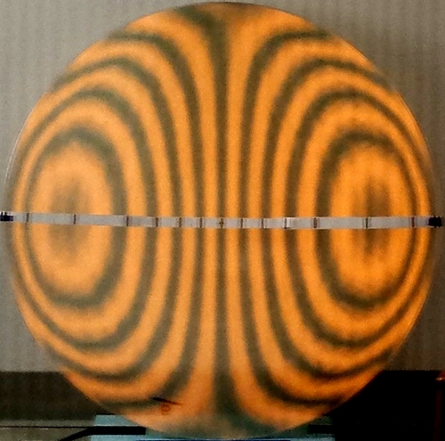
For quick testing I created the Matching Ronchi tape band. It's simply a long piece of paper with felt marks at the precise location that the bands cross the center. I use this to gauge the progress of the mirrors' zones. I suppose one can print out the Ronchi pattern and place it behind the mirror too. Here the matching bands suggest that the broad central area needs more correction (the bands lack sufficient curvature).
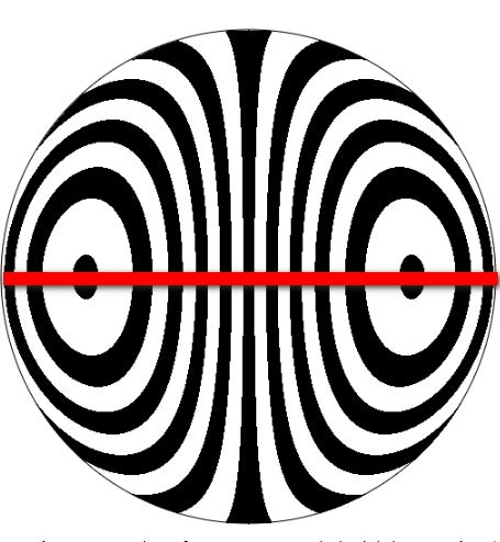
Here are two comparisons of Matching Ronchi tape bands. The first consists of the computer generated perfect band followed by a quarter wavefront deviation at the 70% zone. The difference is clearly seen. The second is, once again, the computer generated bands but matched against a slightly different RoC that minimizes the difference across the entire mirror. The difference is still there.
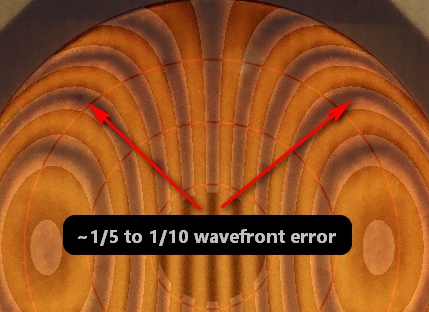
If a band is 'off' from its mark, the tester can be moved laterally, centering the band on the tape mark, noting the difference in thousands of an inch, e.g., by measuring the change angle of the turn of a threaded rod with knob and pointer. This zonal radius of curvature difference can be entered into the standard Foucault zonal measurements spreadsheet to calculate the wavefront error. Using this method, I found, at one point in parabolizing the 30 inch [76cm] F2.75 thin meniscus mirrors that the wavefront peak-valley error was 0.22 waves with the greatest deviation near the 80% zone. I then compared this result to the error portion of the Matching Ronchi test and found the best match Ronchigram to have an error of 0.2 waves at the 70% zone. This method is not intended to give rigorous wavefront ratings but instead to give an order of magnitude feeling to the error at hand.
The Matching Ronchi tape band is ideal for marking the exact edge of the mirror in a Ronchigram. Then the mirror can be precisely matched to the computer generated bands.
The mirror's paraboloidal shape changes so steeply near the edge that I am having trouble getting these zones to behave. I tried a few minutes of finger polishing on this stubborn narrow and high 92% zone. Seems to work! This mirror needs a bit more, and I have to apply the same to the other mirror yet.
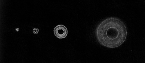
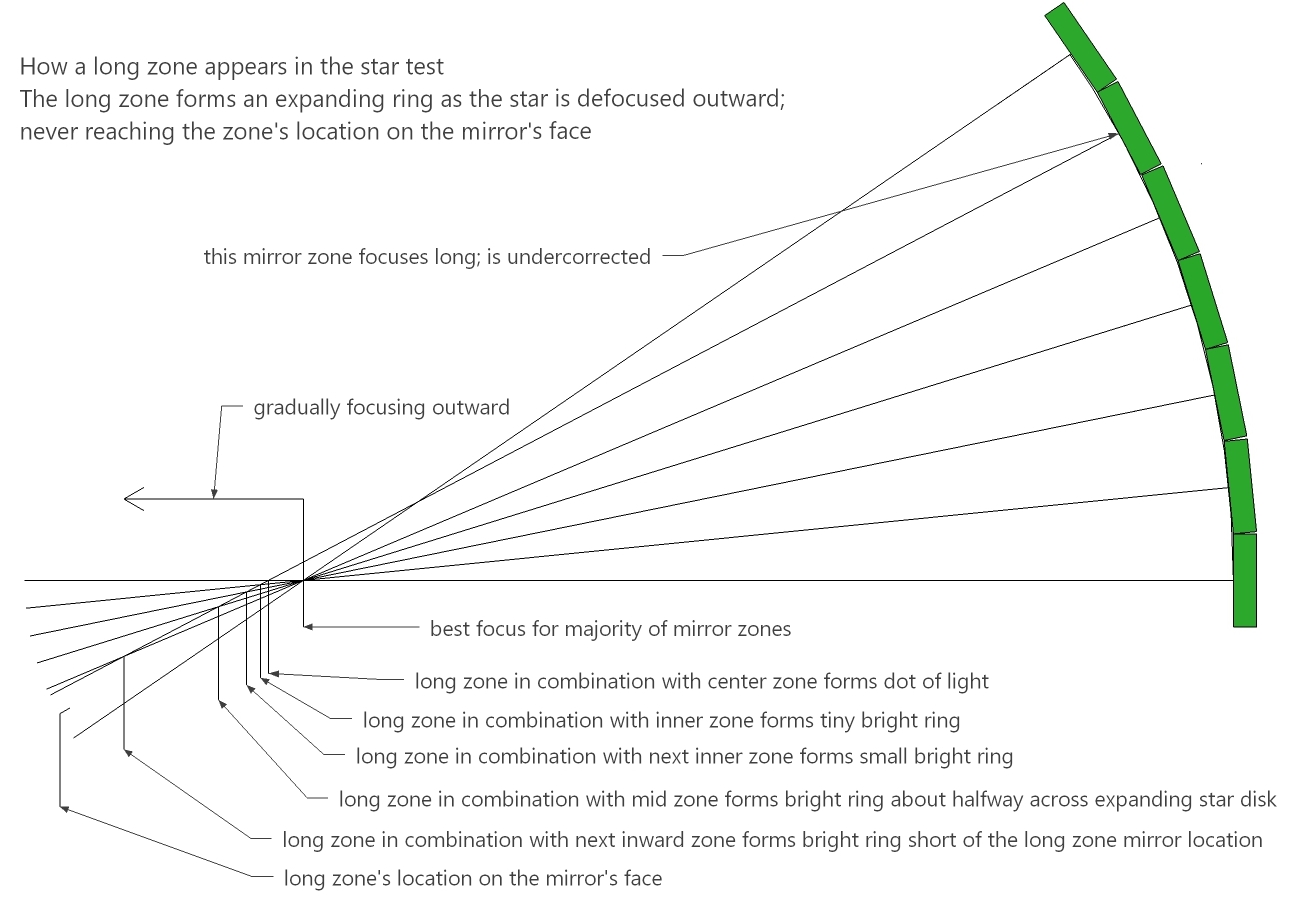
Here is what that low 85% zone looks like in the star test. The low zone starts as a central brightening as the star is defocused, growing in radius but fading in brightness and sharpness as the star is more defocused.
The A mirror was identical to the B mirror. Needing a final smoothing in the outer zones, I added a bit of new soft pitch to a zone then all heck broke loose. I tried to smooth the horrid zigzags but it only turned the edge. Flattening the edge took the mirror back to spherical. I did demonstrate to myself that I can return to spherical using a petal lap. It gradually dawned on me that the pitch had aged so badly that when I added the new softer pitch it caused bad zoning. The old pitch had polished both mirrors an excessively long time to remove small pits at the edge then parabolized both mirrors, so it had been in use for many dozens of hours. I stripped the old brittle pitch and poured a new spider lap. Wow, what a difference. Nice smooth curves with responsive parabolizing.
The return to parabolization for the A mirror took 45 hours on the machine over two plus weeks. And the process was quite automatic. Two adjustments: the first early on when parabolization in the center proceeded too slowly which I addressed by thinning the pedal lap's arms, and then the second to remove a kink near the edge that developed which I addressed by pressing out the pitch in the corresponding zone on the lap. All my large fast mirrors seem to get this defect as the mirror nears full parabolization. Still, overall, I've had more trouble with a 6 inch than the A mirror the second time around!
Close! It is amazing that the two mirrors are so similar. First the A mirror, then the B mirror.
It's been a satisfying and time consuming journey: I have improved my mirror making and testing skills.
Up next is running the Klingon Gauntlet. Using the star test, I need to verify that I have not made a catastrophic mistake in parabolizing the mirrors and I need to check for small amounts of astigmatism. The latter is best done after parabolizing. Then if the mirrors pass these two tests, I use the star test to make final adjustments to the mirrors, taking into account all the optical elements and their supports including primary mirror cell, the diagonal, and my eyepieces. At fast focal ratios, eyepieces can add significant amounts of spherical aberration to the star test and affect the quality of the at-focus images.
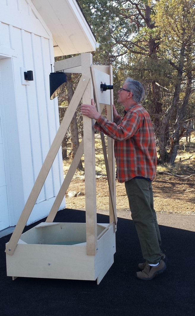
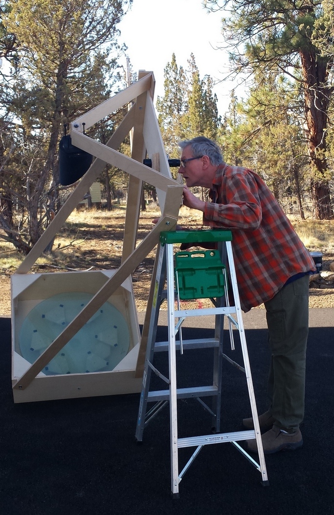
Goal: build a tube assembly that I can prop up and aim at Polaris, a bright star that moves slowly, in order to star test the mirrors.
Date: December-2020
Comments:
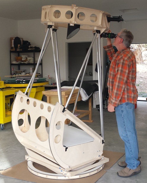
The star test rig. I can just reach the eyepiece without need for a ladder when pointed vertically. That's exciting.
Goal: create smooth and accurate parabolized surfaces to the best of my ability using the star test and Matching Ronchi test
Process: using the star test as a guide, continue parabolizing, varying the stroke and pitch contact as needed
Date: February-2021
Thickness: 0.64 inches
Weight: 38 pounds [17.2kg]
Clear aperture: 29.81 inches (3/16 inch less than 30 inches: the blanks are 1/16 inch less than 30 inches diameter, the bevel is 1/16 inch wide)
Focal length:
Comments:
Initial star tests results: both mirrors pass the snap focus test. These two initial star tests show that the Matching Ronchi test can take large fast thin meniscus mirrors to snap-focus quality.
After smoothing and adjusting overall correction using the star and Ronchi tests...
Both mirrors pass the star test at high power though not perfectly (the 4.7mm eyepiece yields 500x or 17x per inch of aperture, matching the eye's theoretical resolution). Subjectively the mirrors' star tests are close to the star test of my 10.5 inch [27cm] F2.7 which is a great performer in the field for both low power wide angle star fields and high power planetary viewing.
I do not believe I can do better: fixing overcorrection risks turning the edge since there is so much deviation from spherical on these super fast large mirrors. Key was longer 1/3 CoC strokes with accentuated pressure near the edge to smooth the mirror surfaces and then thin spider legs on the lap to increase polishing at the center.
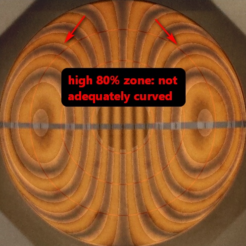
At one point the 'B' mirror had a broad slightly high 80% zone. Here is how such a zone looks in the star test:
How severe is the zone? Here is my guide:
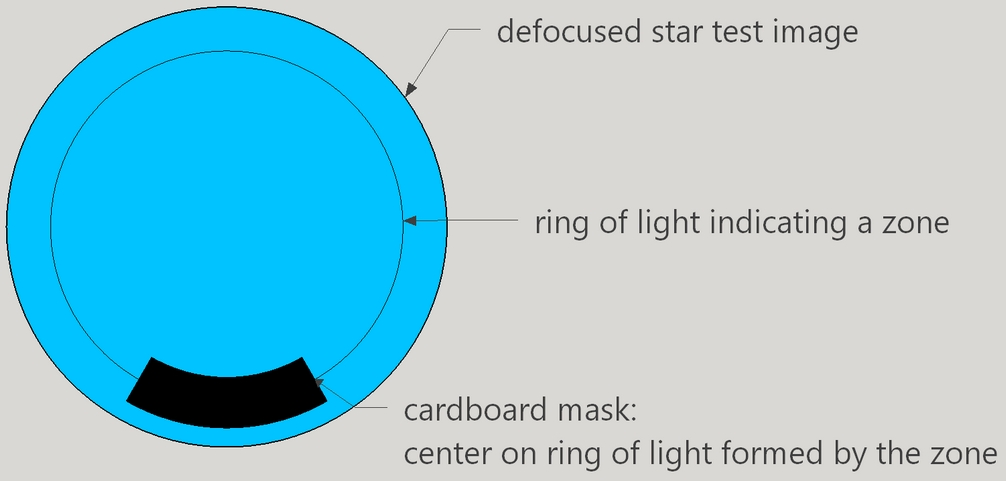
Here is the surefire way to locate the zone using a cardboard mask placed over the mirror while star testing:
And here it is the 'B' mirror's last Ronchigram prior to beginning the star test step, showing the high 80% zone (the error section of my Matching Ronchi test shows the high zone is much less than quarter-wave):
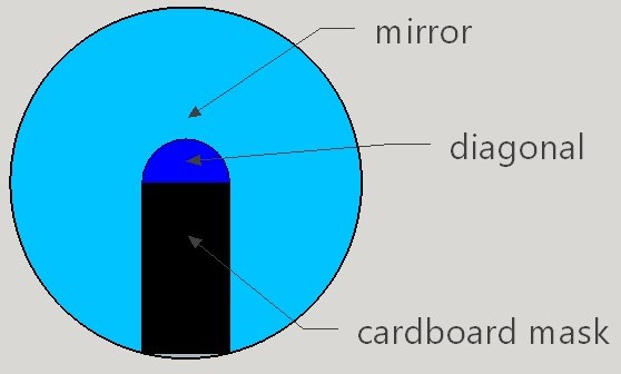
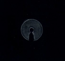
At another point the 'B' mirror had a high or undercorrected central area. Here's the cardboard mask and the resulting star test, demonstrating how the width of the cardboard mask shadow can be used to discern zones:
By far, optical alignment and edge support are way bigger factors. Cooling in the nighttime air does not seem to affect the image. I take the mirror from the shop, drop it into the star test rig, then test immediately. The idea is to avoid the relatively large figure changes due to cooling that the 25 inch F2.6 mirror experienced before I closed off its mirror box.
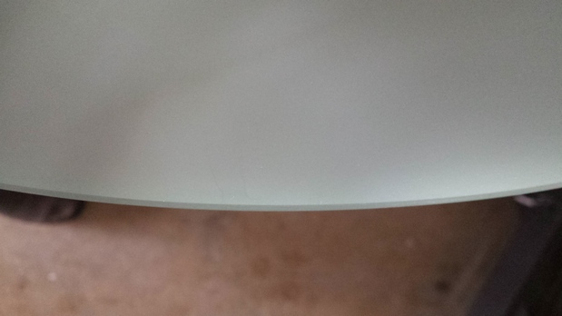
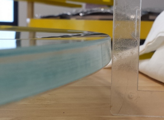
The edge is turned inward because the blank was slumped face down over a convex mold. I did not true up the edge as I didn't think it necessary.
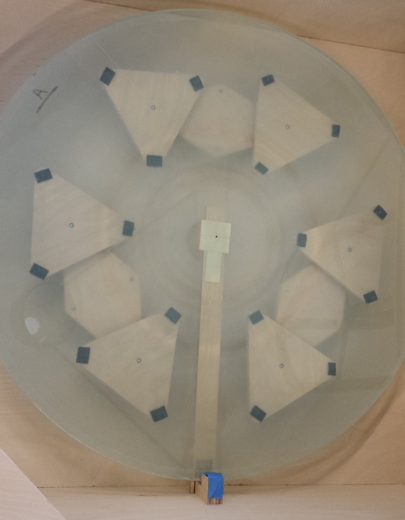
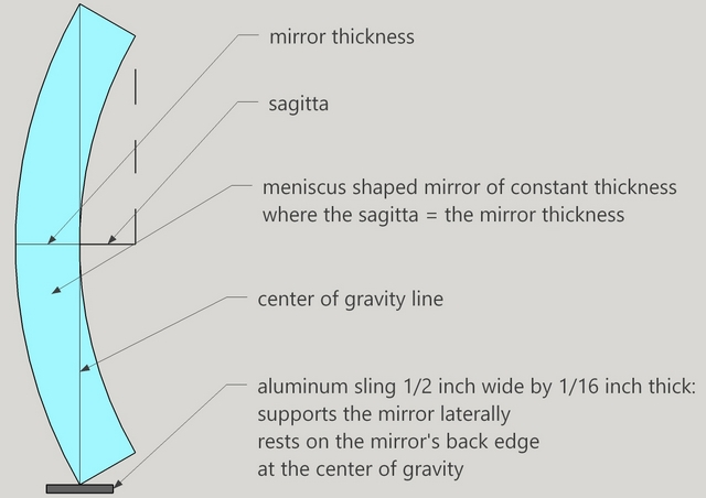
The aluminum sling with a bottom support used as a guide to keep the sling in position. The guide does not touch the sling. The sling rests on the mirror's back edge at the center of gravity.
The two points edge support. Here the single bottom support point does not touch the mirror.
I found during testing that the mirror needs to be fully supported on its back side for the best edge support results. See my comments above in section #17, 'Supporting the mirror for testing'.
Bad collimation is the number one killer of reflecting telescopes. Fast F3-ish telescopes must be a nightmare to align. After all, the area in the center of the field of view where coma is less than one-quarter wavefront is but 0.019 inches [0.5mm].
The advent of reasonably priced coma correctors enabled the high etendue super fast telescope revolution. Nonetheless, coma correctors are not needed at high power and some observers accept the coma at medium and low powers. Through my studies at the eyepiece, I have found one key advantage for coma correctors: they make optical alignment 'easy'.
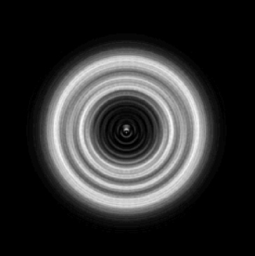
Diagonal offset becomes an issue with fast telescopes. The diagonal breakout shadow appears as soon as the image is defocused and is offset to boot, altering the classic diffraction rings. The offset squishes the inner diffraction rings, altering their brightness radially. While it does not impact image quality, this does makes the telescope appear to be poorly collimated. Placing a mask on the diagonal holder centered on the optical axis (that is, taking into account the diagonal offset) restores the beautiful classic diffraction ring pattern. Here's a synthetic image generated by Rob Brown for F3, 10 waves out of focus, 10mm offset:
Conducting experiments with and without the coma corrector while altering the optical alignment leads me to the following conclusions:
Goal: design a lightweight and portable tube assembly and mounting, keeping the tube assembly under 100 pounds [45kg]
Process: design and optimize in CAD, then build, making minor adjustments
Date: spring-summer, 2021
Comments: now that the mirrors are complete, it is time to build the telescope.
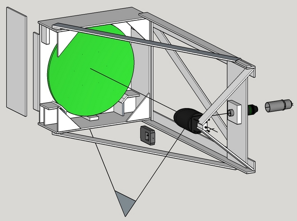
I considered several Optical Tube Assembly (OTA) designs.
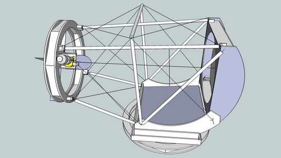
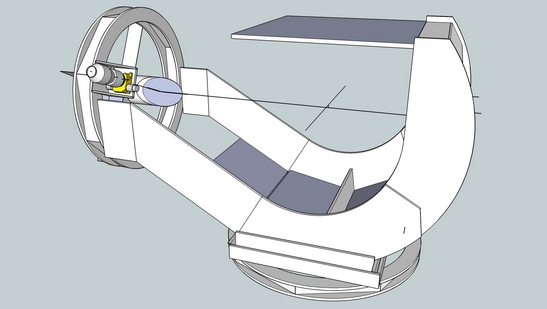
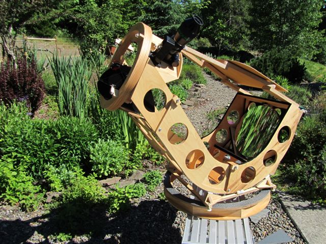
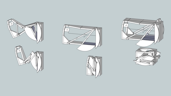
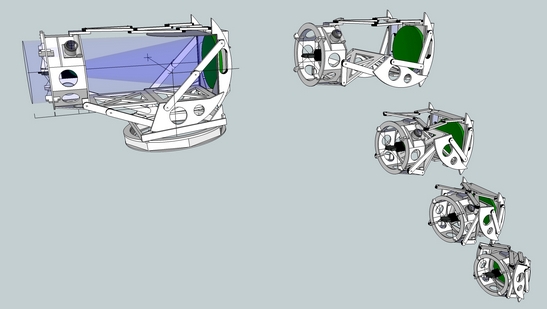
I choose the 'Integrated mirror box with altitude rims' design.
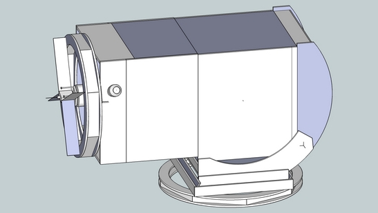
Here's the Sketchup model.
Process: try several lightweight constructs, then build
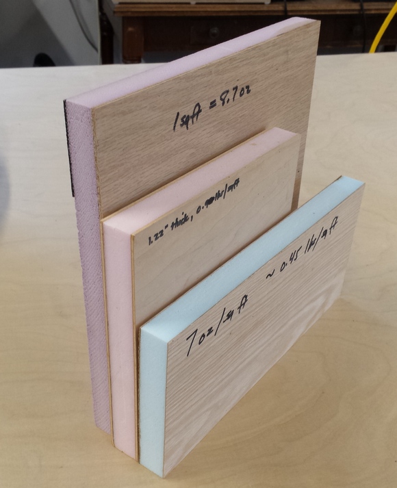
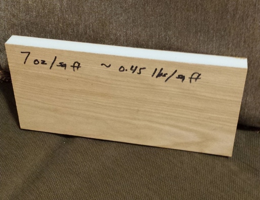
I began designing for foam core construction, where thin wood is glued to both sides of rigid foam insulation, one inch thick [25mm]. But adding interior wood blocks for connectors made it complicated and the wood on both sides did not result in the weight savings I was looking for.
I experimented with thin wood veneer. While the result is lightweight, I did not like the feel. Rubbing my fingers across the grain revealed waviness which is in inherent in the veneer. I did not try vacuum forming - perhaps that would help.
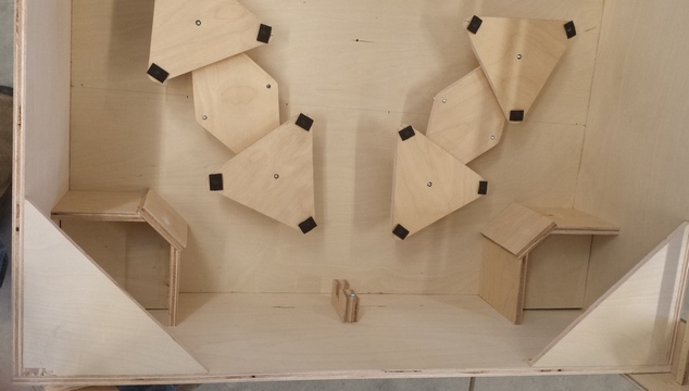
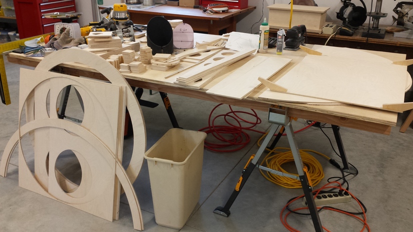
I am building the tube assembly from 1/4 inch Baltic Birch. Thin Baltic birch is lightweight but flimsy, so I am using a frame and skin design like an monocoque airplane to make stiff, lightweight structures. Here are the parts for the tube assembly, cut out and ready to assemble.
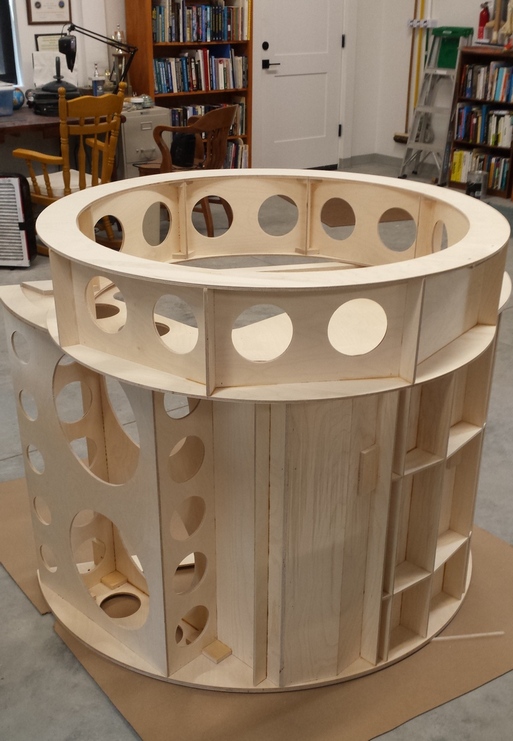
And here is the assembled mirror end and upper end. These assemblies are rigid and light, if not a bit involved with all the ribbing.
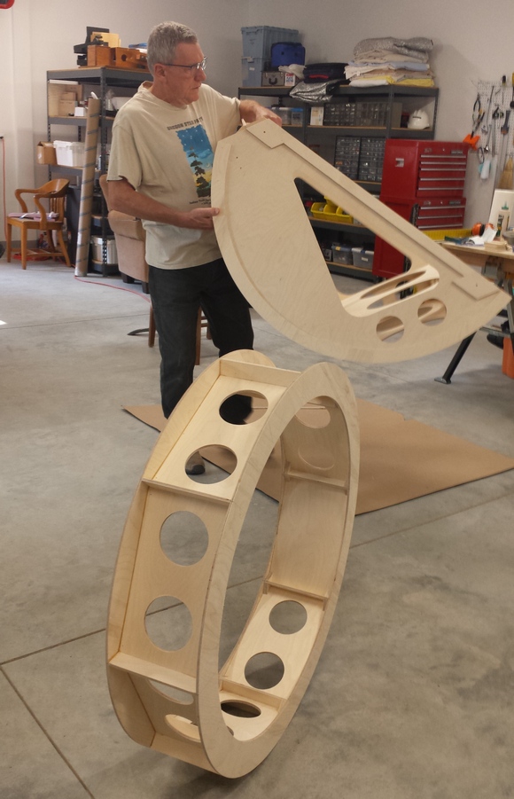
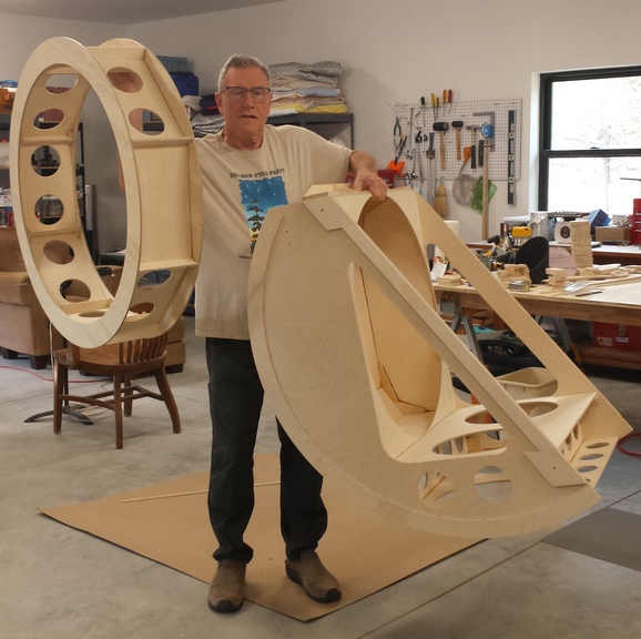
The mirror end weighs 30 pounds [14kg] and the upper end weighs 9 pounds [4kg]. Add in 8 pounds for the trusses [4kg], 2 pounds for the focuser [1kg], 2 pounds for the diagonal holder and wire spider [1kg], 1 pound for the finder [1kg], 38 pounds for the primary mirror [17kg] and 5 pounds for the secondary mirror [2kg]; adds up to a total weight of 95 pounds [43kg].
Cutouts save me 8 pounds [4kg]
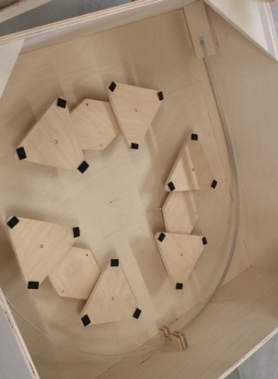
Testing of various mirror supports on the test stand and in the star test rig demonstrated that there is no discernible distortion with an 18 point back support with edge sling. Pictured is the star test rig's mirror cell.
The 18 point flotation back support is a highly successful design based on a ring of six triangles. Three bars hold the six triangles. Each bar is kept aligned and adjusted by two alignment bolts. Each triangular support point carries about a little less mirror area as each support point on my 13.2 inch [34cm] F3.0. Contrast to John Dobson's 18 point support design.
See my mirror bending study comparing mirrors.
Note that the edge support goes through the meniscus mirror's center of gravity by virtue of touching the mirror's back edge.
I build alignment into the telescope so that very little adjustment is needed after construction. Here's the focuser check. Note that the laser is hitting the target on the opposite end of the upper ring - nice! This helps separate the issue of aligning the focuser axis to the primary mirror axis from the issue of centering and rotating the diagonal. And thereby using a smaller diagonal that gives me less obstruction even when including the coma correction intrusion. The intrusion does not affect the images.
Here's an optical study by Rob Brown on these kinds of intrusions.
Pierre Lemay invented a helical Crayford focuser and built a three inch model for me. This design utilizes the three inch TeleVue P2 coma corrector's body as the focuser tube. I intend to use this focuser primarily for wide field digital imaging. The adapter is perfectly aligned on the target and took a bit of custom woodworking. The 3 inch to 2 inch adapter is inserted so that I can use my alignment laser. I modified the AstroSystems diagonal holder. I got rid of the heavy aluminum plate that holds the 4 adjustment screws. Wires will make the adjustments for me. And I got rid of the heavy phenolic base plate, replacing it with a cored lightweight wood piece. I shortened the diagonal shroud to reduce the cantilever of the mirror. All in all I saved two pounds [1kg] of weight and brought the diagonal inward a couple of inches [5cm]. I decided to go with my 8 wire spider and Crayford focuser as I have done for a number of years. I considered a new wire spider arrangement coupled with a sled focuser. I've used sliding focusers on a couple of telescopes. They have advantages; the disadvantage is that the diagonal has to travel with the focuser. Here are images of my new design that, in the end, I decided against. Here is the alignment jig showing how the diagonal holder is nestled in the jig. The jig attaches to the upper end so that I can attach the wire spider. And here is the 20 gauge wire spider immediately after installation and alignment. It works, meaning that I am able to align the secondary by adjusting the eyebolts that hold the wires, and the laser dot stays perfectly centered on the mirror cell's target as I move the scope from horizontal to vertical and as I squeeze the upper end. I have used wire spiders in four of my previous scopes: 20.5 inch [52cm], 10.5 inch [27cm], 13.2 inch [34cm] and 25 inch [64cm] telescopes. An unexpected benefit of the wire spider, then, is that it serves not only to hold the secondary but also doubles as the alignment mechanism.
Essentially, for the wire spider and focuser board to be stiff, the upper end needs to be stiff. My test for this is to move the scope by grabbing the diagonal holder in the middle of the wires. The scope should move nicely while the laser collimator et al remains steady.
I use the QuInsight finder. It has the advantages of a large offset, an extra wide 20 circle, a big window to look through from a distance and the ability for the reticle to rotate in order to line up a star hop. I use a hammer with a long threaded bolt to tap the inserts into the aluminum tubes. I press sideways on the bolt when needed as I hammer it down to keep the insert straight. Here's the trusses assembled. I use Aurora Precision parts. Nice and stiff! The eyepiece can be reached at zenith by standing on my toes so I will only need a short-height-platform to stand on. The upper end seems especially strong. I attribute that to the lateral pieces (ribs) between the octagon shaped spreaders. The problem with the Dobsonian mount is that hand pushing the scope away from your eye works fine when the scope is pointed horizontally; not so fine with the scope is pointed vertically. Pushing when horizontal matches perfectly with the azimuth axis: the scope rotates around in a circle. Pushing when vertical does nothing. In fact, one must grab the upper end with both hands and twist the scope in azimuth to get it to move. This is no different than the awkward movement of equatorially mounted telescopes near the pole. Didn't like it then - don't like it now. The fix is to add a third axis in the guise of another altitude axis at 90 degrees to the initial altitude axis that matches this push perfectly. A good design then switches naturally between the two when the scope reaches 60-75 degrees elevation. Here are CADs of my 25 inch F2.6 scope followed by an image showing the scope tipped in the second altitude axis followed by a cutaway image showing the dual flex rocker. The third axis also gives me the option of changing the eyepiece angle and altitude. Tipped down while at zenith, I can reach the eyepiece without a step stool. Imagine, a 30 inch no-ladder telescope!
Here is the base flex ring with Alucobond top and bottom layers. The ring is very stiff over arcs but can be made to bend ever so slightly with heavy pressure across its diameter. By settling the base ring into the ground or by using a few shims, the base ring becomes very rigid. The base is short and thin in order to place the mirror's bottom edge, residing in the mirror box, as close as possible to the ground to minimize eyepiece height. The alt-az flex rocker's job is to hold the lower azimuth bearings underneath the altitude bearing points. The bearing points are held rigidly in relation to each other, despite the flex rocker being easily twisted in my hands. By stacking another flex rocker at right angles, we achieve 3-axis movement. The alt-alt (contrast with the alt-az flex rocker) flex rocker holds curved arcs to pivot on while positioning the well known altitude bearings for the mirror box with its large scale altitude rim to rotate in. The last image shows the rocker upside down, displaying the aluminum strip covered arcs that allow for movement in the 2nd altitude axis by a total of 15 degrees (+-7.5 deg) and allow for movement past the zenith of 7.5 degrees. Each axis has a set of interchangeable Teflon, Nylon and ball-bearing assemblies, along with keeper bearings. Here are some pics of the Teflon and ball-bearing assemblies. I can control the friction of movement by using ball bearings in place of Teflon (PTFE) pads. By replacing one, two or three pads, I can correspondingly lower the effort to move the scope. I've used this approach with pleasing results on my 24 inch [61cm] F5.5 and my 25 inch [64cm] F2.6 telescopes.
Tests with heavy weights on the double flex rocker flex base ring show that with two ball bearings and two Teflon pads the friction of movement at the eyepiece with the scope pointed 30 degrees up from the horizon will be about one pound [0.5kg] of friction. For a single Teflon pad and three ball bearings the friction is halved. At 65 degrees above elevation the friction is doubled compared to 30 degrees above elevation.
I took the opportunity to revisit telescope motions considering that I have aluminum strips and painted aluminum Alucobond as bearing surfaces. Besides the friction of movement, critical to a good feel at the eyepiece especially at high power is a smooth creeping motion. To test, I place a weight on the sample material, then strive to imperceptibly move the weight, looking for any disqualifying jerky motion. I discovered that the pebbly nature of the material is key; the actual material less so. Any type of smooth surface, even Formica, tested relatively poorly. Here are three surfaces that test equally well, no jerky motion, just a buttery smooth very slow motion, using a Teflon pad. People also report that the 3D print material PTED works nicely with Teflon.
For the smooth aluminum surfaces, I discovered that polished Delrin and a type of softer translucent plastic akin to plastic sheeting worked well. The very best appears to be a flattened Nylon cable clamp. I tried many plastics including Yogurt lids. The vast majority had some jerkiness. Here are four materials, clockwise from the left: Nylon (charcoal), Teflon (white), UHMW (the off-white piece) and Delrin (the small black piece). They all work well with a smooth start to the motion (no jerkiness) and nice smooth resistance to movement. UHMW is inexpensive and Delrin is very hard. I'm going with Teflon as it slides with slightly less friction than the Nylon though I like Nylon's increasing resistance to faster movements best.
Since the altitude rims of the mirror box extend below the centerline, since the eyepiece, coma corrector, focuser and finder are above the centerline, and since the telescope uses three axes, the scope must be balanced in all three axes. I calculated the offset center of gravity using my NewtDesigner then built a box to hold ankle weights. For wheeling the scope around, I built a trolley. Though the scope is not impossibly heavy, it stretches way out in front of me when I pick it up from the rear, making carrying it around quite awkward. The trolley breaks apart into a forward section and back section. Lifting up a section allows me to slip in the wheels. The rear wheels are optional. An important design aspect is that the trolley lifts the mirror box (for that matter, the rest of the tube assembly) up off the double flex rockers and base ring, protecting the ball-bearing and surfaces that they ride against. Setup time from the moment I walk into the shop to the time that I am turning on the finder with eyepiece and coma corrector inserted is exactly five minutes. The mirror is ready to go because of its thinness.
However, my goal of breaking down the scope to easily lift into my mid-sized SUV is unmet. The 75 pounds [34kg] is lightweight enough but the sheer bulk of the mirror box and altitude rims is daunting.
I have two goals for the baffling. Block stray light and help prevent the optics from cooling to the night sky and dewing over. The silvered coating on the primary mirror needs extra protection. Isolating the optical path from night time breezes also stabilizes the mirror's optical figure. I tried both ripstop nylon and spandex and liked the spandex for its stretch better. For the mirror box I am using sign board with sticky felt covering for the interior baffling that is painted silver on the outside. This is the easiest telescope I've ever aligned. Since I built the focuser adapter plate aligned to the upper end, I did not have to shim the focuser or adjust the diagonal underneath the focuser. I adjusted the wires holding the diagonal a couple of iterations until the laser pointed at the primary's center. Then it was a mere three adjustments on the primary mirror to aim the laser right back on itself. The whole affair only took seconds.
Does the telescope focus? Because I design a short in-focus travel distance in order to keep the diagonal as small as possible, it's important to place the focal plane precisely. Additionally, I check that the mirror cell is working well. Finally I test the trolley transport design in the dark under the stars in the cold.
Results: the mirrors check out just as they were in the final star test meaning that the mirror cell is working perfectly. The scope moves smoothly with nice balance. The trolley takes very little effort. However, the scope is focusing a bit too far inward by a 1/4 inch [6mm]. I set the in-focus travel distance of 3/8 inch [10cm] for near-sighted people but the in-focus travel was only 1/8 inch [3cm]. Investigating the next day, I see that I had set the mirror cell back in the mirror box - I build in a fair amount of latitude. I rather like it in this position, so easiest for me, since all else is dialed-in, is to shorten the truss tubes a smidgen. Subsequent check under the stars shows that the focus is exactly where I want it.
Goal: coat the mirrors with a highly reflective metal for maximum light
Process: use the Oregon Scope Werks' silvering process
Date: Dec-2021
Thickness: 0.64 inches
Weight: 38 pounds [17.2kg]
Clear aperture: 29.81 inches (3/16 inch less than 30 inches: the blanks are 1/16 inch less than 30 inches diameter, the bevel is 1/16 inch wide)
Focal length:
Comments: the cost (close to $2000 for each mirror for an enhanced aluminum coating) and the fear of shipping the mirrors back and forth across the country is daunting. Silvering the mirrors once a year seems more practical. Plus this gives me the option of touching up the mirror's figure in the future, should I decide that something in the image bothers me and that I can do something about it.
Here is the silvering jig. It supports mirrors of various sizes and pivots for cleaning and silvering. I used the Oregon Scope Werks silvering process. The second attempt turned out stunningly beautiful. Not a hint of white or blue haze. Not a scratch on the glass from polishing, parabolizing or silvering: just a perfectly brilliant silver looking mirror. Instrumental was Howard Banich's guidance. Howard is the Jedi master of silvering. The first attempt apparently failed because I didn't clean the precipitated calcium carbonate from the glass well enough. The dry air of central Oregon was quickly evaporating the distilled water wash leaving behind an invisible layer of calcium carbonate. The second silvering attempt I doubled down on wiping away the calcium carbonate using cotton balls with lots of distilled water over and over again until the glass began to squeak and squeal. This resulted in a most beautiful coating. The process including the failed first attempt took about six hours. Sounds like a lot of time but it flew by quickly. The process demands that the next step begins immediately upon completion of the previous step, keeping the glass wet at all times with distilled water. A lot of spraying! In fact I used five gallons of distilled water for the two silvering efforts.
Placing the mirror in the silvering jig followed by cleaning the mirror with precipitated calcium carbonate then Howard inspecting for cleaning issues; finally, gearing up for the spray silvering itself. First attempt - failure! Apparently the precipitated calcium carbonate dried on the mirror's surface and wasn't washed away with the distilled water sprayer. Second attempt - success! This time I wiped the surface over and over again with cotton balls with liberal distilled water spray until the glass started to squeak wonderfully. Silver begins to form quickly; it is important to keep the mirror wet at all times. I finished with 10 minutes of Midas soak, a silver protecting compound. Here's the coating so fresh that a few water droplets still remain. Center spotting with a felt marker. I can center the laser collimator beam on the felt marker black dot better than a notebook white ring. Protecting the mirror with an anti-tarnish cloth draped over the mirror and dehumidifiers. Two and a half years later, I resilvered the mirror. The original coating's reflectivity was still decent at 92% but it the coating had begun to look less than pristine.
At night, shine a flashlight down onto the primary mirror. How does it look: good, bad, ugly? A clean look with no scatter is a passing flashlight test. Needless to say, many mirrors in the field do not pass, yet give excellent images through the eyepiece. I use the flashlight test to judge cleanliness and mirror coating quality.
Coatings can and will fail, sometimes gradually, rarely catastrophically. A new coating on my 24 inch [61cm] F5.5 was ruined in a single night during a star party for Halley's Comet because we were enveloped in smog. The next morning blemishes appeared, soon growing to cover much of the mirror's surface. On the other hand, a 20.5 inch mirror [52cm] that was coated with enhanced aluminum still looks good after 30 years!
The silvered coating looks cleaner with less scatter compared to enhanced aluminum coatings. The flashlight test appears 'deeper'. To the unaided-eye, the coating looks clean with that feeling that one can fall into the mirror. Indeed, I have bumped the mirror several times because the surface looks further away or deeper than it is. Some small cosmetic blemishes appear mainly at the edge as the silver coating ages.
Goal: see how the telescope performs under the stars in a variety of conditions.
The value of a telescope is the observations and images made. Can I see something new, something that I haven't seen before?
Here is my first light report, after silvering the mirror during the afternoon.
Well, wow.
Despite the most horrible seeing one can imagine, the views were really something special. The warmth of the star colors - so many stars shining with hues. I know it's 30 inches of aperture but there is something more going on thanks to the silvered coating. Then there is the inky black contrast right up to the edge of the stars and the incredible nebulosity that is everywhere one looks. The Pleiades was the highlight for me. The Merope nebula cascading down the field of view that fit the core of the Pleiades (image that in a 30 inch scope - I marveled all night long at the wide fields). Then a nudge outside of the core showed the bright dusty Pleiades Bubble like never before. Wow.
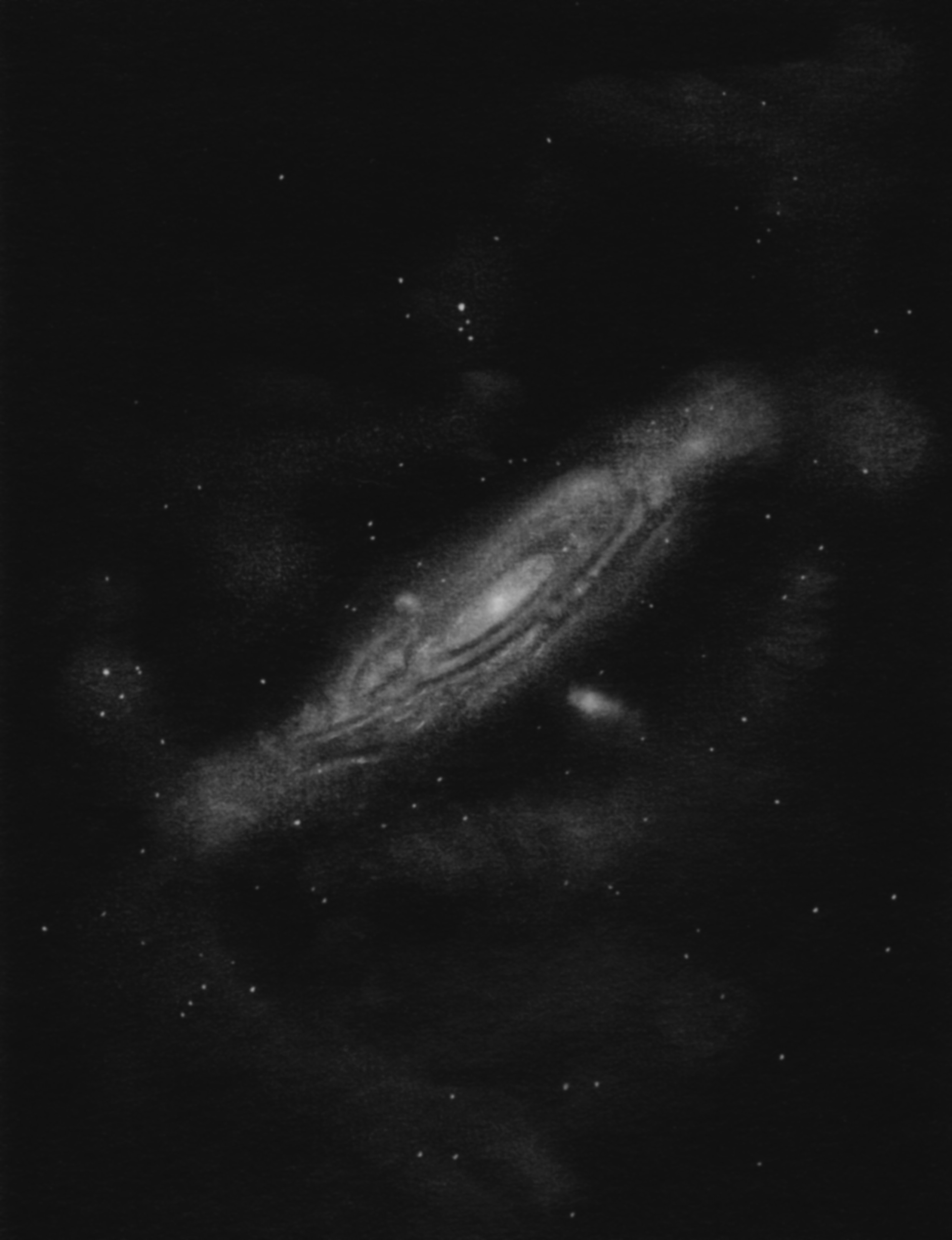
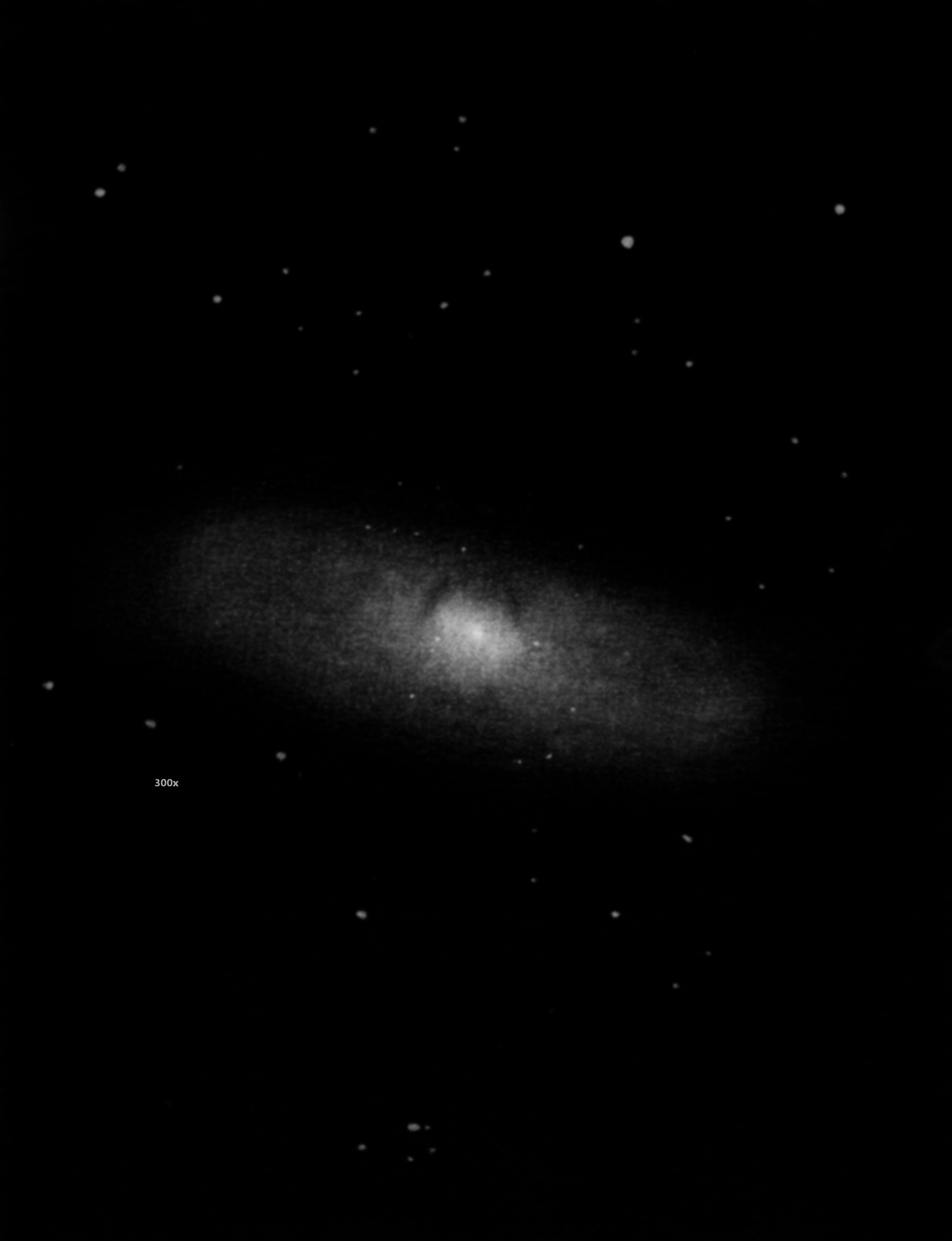
The Andromeda Galaxy went on and on, field after field, with surprising detail in the spiral arms. That was another special view. The companion galaxy was tremendous - reminding me of the view in Swayze's 40 inch, where the companion galaxy was as dramatic as the Andromeda Galaxy is in smaller scopes - definitely the territory of big scope observing. I had trouble finding the North American Nebula. Is that complex glow it? No, how about the next field over? Whoa, that's it - it was massive with interesting detail.
The Orion Nebula - the colored hues obvious and the glow of nebulosity particularly to the east would not end.
The scope performed as advertised. I especially like the three-axis motion. We did a lot of observing near the zenith: it was so natural to move the scope in the two altitude axes when aimed high.
The one negative issue was that the mirror looked pretty overcorrected. It bothered me a lot. And I thought later while sleeping that this was not the star test that I parabolized the mirror to. It had to be the thermal upset of hours of handling the mirror while silvering, the sun shining on the mirror during the afternoon, the hair dryer that I occasionally turned on high to evaporate the pesky water droplets that hung on valiantly.
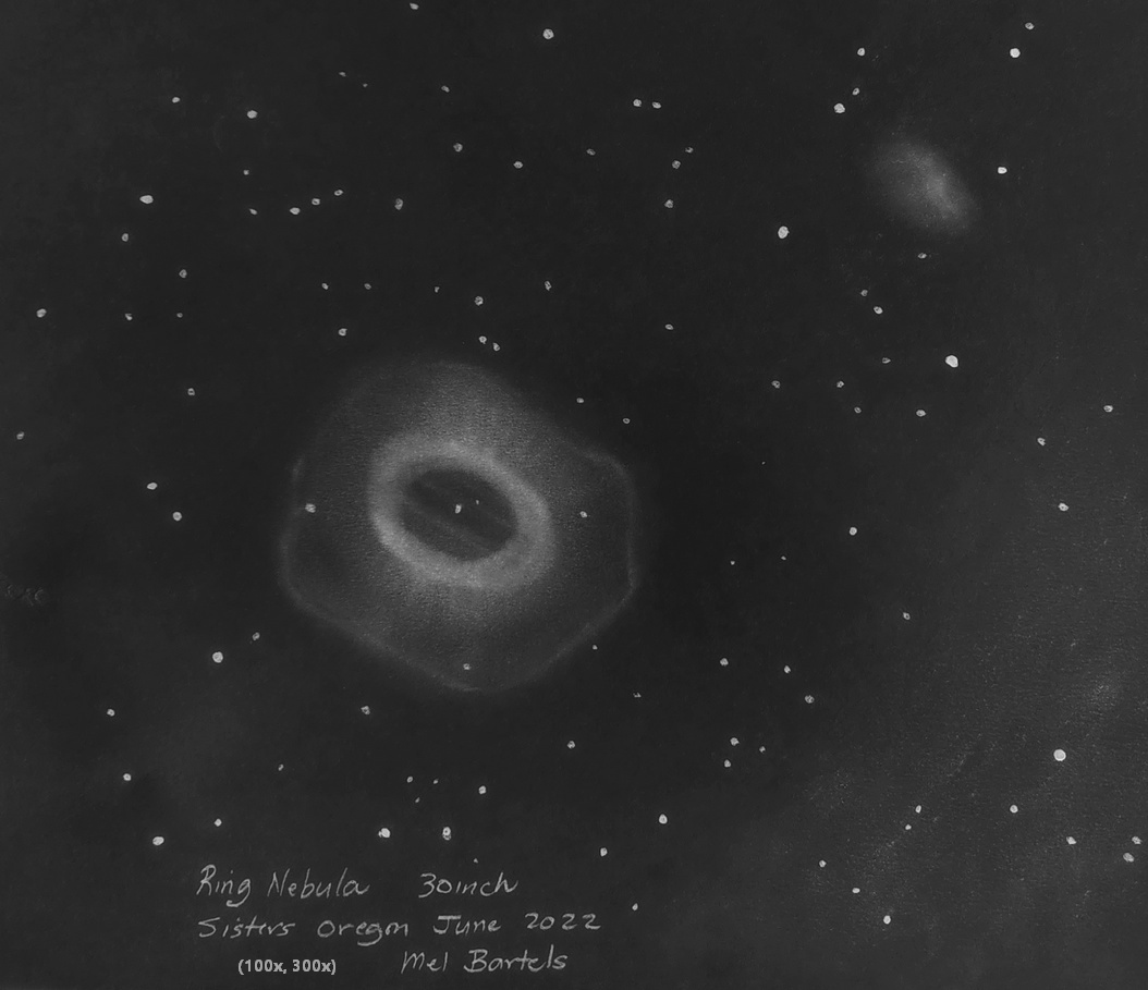
The next night the skies cleared, mostly, so I assayed the scope out and took a second look. Much better! The mirror passes the diagonal breakout test with a 1.5:1 to 2:1 ratio on the overcorrected side. Elipson Lyrae (the double-double) was nicely split with black lanes between each pair (but wow the bright glare from the stars is something else). The Ring Nebula glowed green-blue with the central star a continuous speck of light. Did I say much better? Order in the universe is restored. This goes to show that these ultra thin meniscus mirrors need thought through mirror cells and careful thermal management.
The observations made with a telescope determine its value. This scope is already paying dividends. I'm eager to see new objects and re-visit all the old ones. So that's my first light report. Wow - a real high.
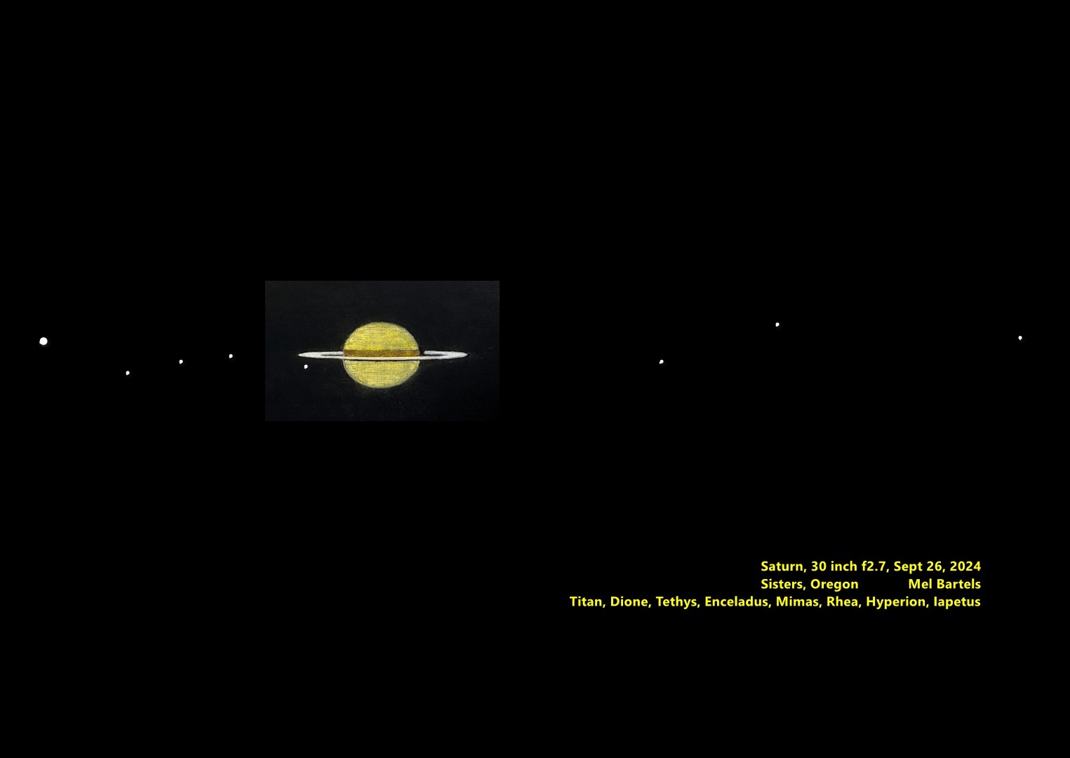
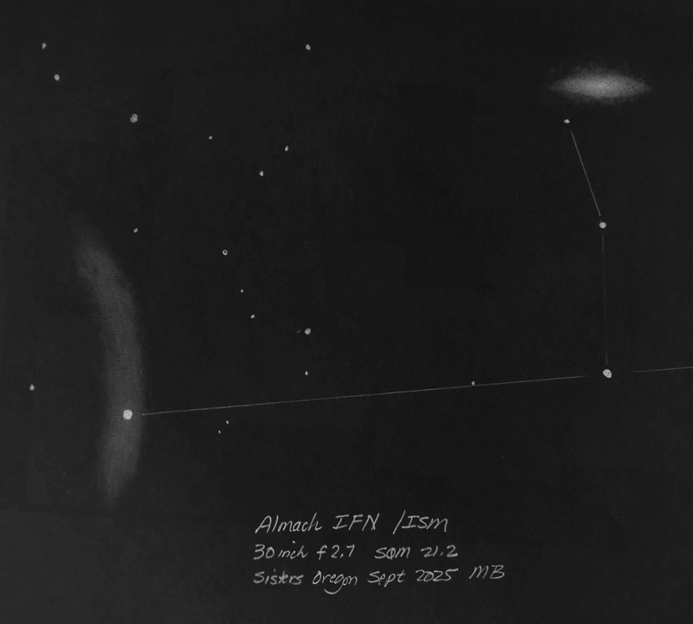
Conditions were mostly clear, with several contrails drifting by occasionally. The SQM showed 21.3, transparency was so-so, and the seeing was mush.
Mel chose the North America Nebula as his first light object. We used both his 21mm Ethos and my 25mm ES 100 degree eyepiece along with NPB and OIII filters. With the 21mm and filters the bright and dark nebulosity was astonishing, but the wow-factor got bumped up a notch with teh 25mm - really the finest view I've had of the NAN and the Pelican. The 25mm gives a true field of one degree, which paired with 30-inches of aperture is an incredible combination.
I forget the order in which we looked at objects, but here's what I remember (I'm really tired after driving home!)
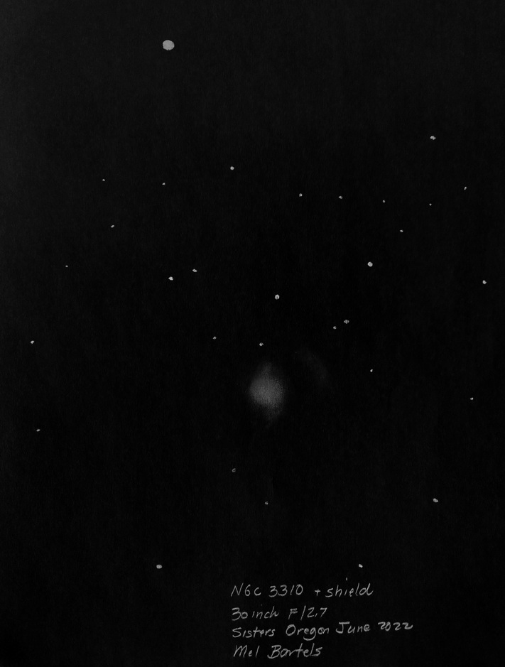
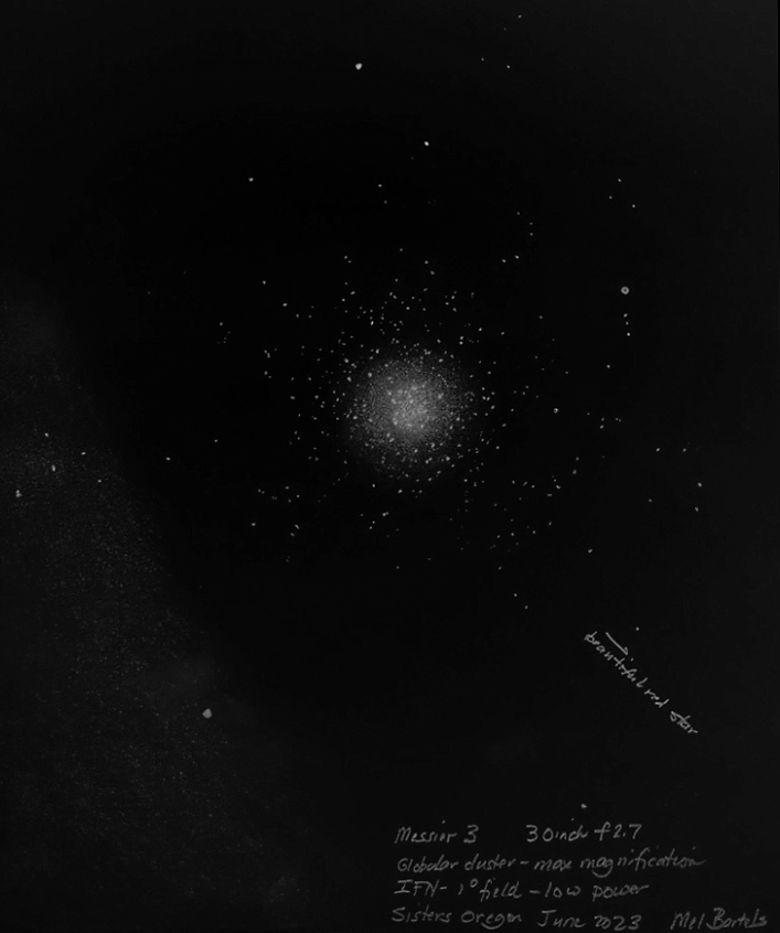
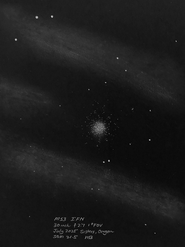
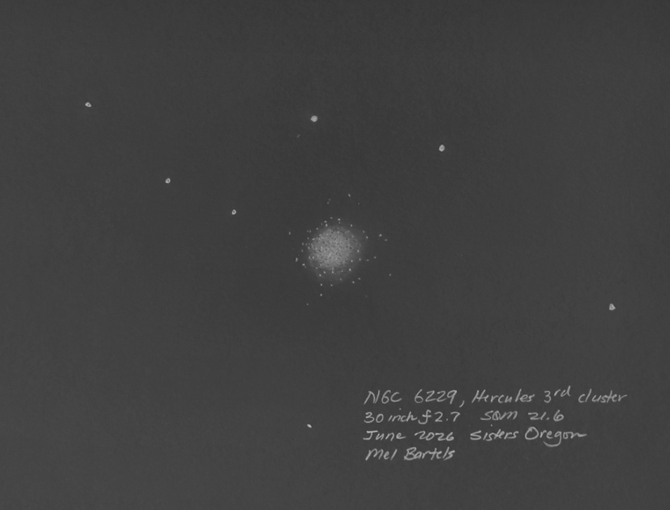
M15 - The only disappointing view of the evening, and only because of the mushy seeing. Very bright and condensed, with a surprisingly bright IFN right next to it.
M31 - My first glance didn't indicate a great view, but after just a few seconds, it became apparent that the inner dark lane was sharply curved toward the nucleus - I'm pretty sure I've never seen that before! The lumpy texture of M31 spiral arms was wonderful as were M32 and 110 - all just stunningly beautiful in the 25mm.
M33 - This was my request, and wow, was it an amazing sight. in the 25mm it framed the entire galaxy - including its two extended spiral arms and nearby IFN's. At higher powers the fluffy texture of the spiral arms and bright patches of OII regions throughout blew me away.
Pleiades - We could almost fit all the brightest stars in the FOV with the 25mm eyepiece, and the surrounding nebulosity was so obvious. Also - practically no diffraction spikes from the bright stars - wire spiders rock!
Double Cluster - Probably the most beautiful sight of the evening. The clusters are perfectly framed with the 25mm which was stunning enough but what really got me were the star colors. We'd been remarking on star colors all evening, but they really stood out here, as well as the contrast. Black sky right up to the colorful stars.
M42/M43 - We caught them just as they cleared the roof of Mel's shop, so not only were they really low in the sky, the heat from the shop's roof was making the overall poor seeing even worse. No problem though, there was tons of color throughout M42/42, with 43 looking the reddest I can ever remember. The Orion Bar was a nice orange and Theta 1 Orionis C - the brightest star of the Trapezium - is a lovely yellow contrasting with the blue of the other three main stars of the Trapezium. The Trapezium nebulosity was a lovely turquoise, and the bat wings a brick-red.
To illustrate how poor the seeing was, when neither of us could see the E and F stars, Mel got out a 12-inch off-axis mask, transforming his scope into an unobstructed 12-inch f/7 - and still no trace of the E and F stars.
Horsehead - Although not the best view I've ever had of the HH, it was remarkably good for the conditions, and was a view I think that a majority of observers would be astounded by.
A few other comments.
The mirror cooled much more slowly with the new coating than it did during Mel's star testing the bare glass mirror. That kept the mirror's figure noticeably over corrected, but it was gradually improving during our fairly quick observing session. We started observing immediately after he rolled it out of his shop, so it had no time to cool off. He said the correction was quite good during his bare glass star testing with a 6mm Delos, so the glass is fine, it just needs more time to cool, or a way to cool faster.
With Mel's new light baffles creating a deep mirrorbox-like environment, with a sealed back, the mirror had a tough time acclimating, and Mel is going to experiment with opening a vent in the back and possibly adding a cooling fan.
The combination of 30-inches of aperture and a one degree true field is beyond what I can adequately describe right now - my brain is as mushy as the seeing last night. I think the edge performance is better in the 30-inch that it is in my f/4 28-inch scope. Mel had been considering getting the 25mm ES 100 degree eyepiece, but at the price they're going for now he was hesitant. He may have already placed an order for one of his own after seeing how well it worked last night.
The 30-inch is really user friendly, especially for me. I don't need a ladder, and the third axis of rotation of his mount works so well near the zenith. Wonderful ergonomics, and solid as a rock.
One of Mel's goals while designing his scope was to build in the collimation - and amazing to me, he succeeded! When he put the silvered mirror back in the scope he checked collimation with his laser, and it wasn't just really close, it was dead on. He built in adjustments to his diagonal mirror jig so he could get the diagonal positioned exactly right before adding the wires, locking into place. there isn't a hint of movement to the diagonal - if you wanted, you could grab it to move the scope around with no change to the collimation! Drop-dead amazing.
I'm sure I'm forgetting a bunch of stuff that's equally incredible - I'm really tired now - but I'll end by noting that if anyone on this list is a Jedi Master, it's Mel. His scope looks simple and easy to make, but the level of sophistication and craft is crazy. A 30-inch f/2.7 meniscus mirror that weighs all of 38 pounds? And made two of them? Give me a break, but then the Masters always make it look easy.
"Do or do not, there is no try."
Howard Banich
Great skies last night: the Zodiacal Light is brighter than the Milky Way and stretches past the zenith. Last night was 32F, 60% humidity, and no wind all night long. I'm taking my time with the 30", learning what looks exceptional. The scope is working great - very pleased - a joy to use.
The observing aspect that's really standing out is the color in the nebulae and stars. M42 for example is intensely colored with blue-green hues and reddened wings. Surprising was how red M43 looks. The Running Man in contrast is blue.
The Merope Nebula is brownish hued - definitely differently colored than the rest of the nebulosity that streaks in and out and around the Pleiades. M31 has a yellowish core. M110 is a distinct galaxy: large and detailed in its own right.
M81 was surprising: bright, detailed, and the spiral arms just wound around and around and broke into detail. Lots of IFN detail too.
The Horsehead, in contrast to Jerry's view, was again uninspiring. It's too big in the 30" and I couldn't really see the flame coming off the head. I will keep trying on this one.
The California Nebula was the most unexpected - streamers curving all over the place, stretching on and on.
Star clusters are in your face bold. 7789; M35 and the tiny intensely sparkling 2158 in the same field.
The contrast in the scope is wonderful: jet black right up to the edge of the stars. I kept going back and forth on eyepieces: every eyepiece gave something unique. And the silvered mirror looks brand new after two months. The flashlight test is wonderful - deep deep - not like the shallow dusty typical look.
The 30 inch is turning into a galaxy killing machine. Last night no matter where I pointed the scope there was galaxy after galaxy in every field of view and variations in background glow - IFNs. Scanning through the Virgo Cluster like I might take an RFT and scan through the Milky Way was just astonishing: so many galaxies but each galaxy had its unique shape. I literally was galaxy hopping. I felt like there was no limit to what I could see.
I'm learning how to use the passive vent that I built into the back of the mirror box. It takes me about 5 minutes to roll out the scope and uncouple the trolley and get an eyepiece and coma corrector into the focuser. The star images are good right from the start. After 20-30 minutes, the star test shows overcorrection beginning to form, so I open the 2 inch vent and literally within 2-3 minutes the correction backs off and I get perfect star test images. I then close down the vent to 1 inch and the mirror maintains correction for the rest of the observing. If I open the vent preemptively ahead of time, the mirror tends to stay slightly undercorrected for the rest of the evening. So the key is to catch the change in correction, then adjust.
Star images are perfect little dots/specs even near the horizon, which is surprising considering how thin the mirror and that I'm using a passive sling. I have yet to adjust collimation since I first built the scope.
Finally I got to see what the 30 inch F2.7 is capable of! Stars at all magnifications were steady dots and pinpoints, depending on brightness. Looked very refractor like. Epsilon Lyrae was beautiful. Steady intense spots of light with equal black between. Two stars inside M57 at high magnification. Even down on the horizon M6-7 area sported tight unmoving stars.
I had been getting a little frustrated recalling memories of my last 30 inch, a Pyrex 1.5 inch F4, where the stars suffered constantly from seeing. I eventually got rid of the 24 inch F5.5 and the 30 inch in order to build the 20.5 inch F4.8. The idea was to make a slightly smaller high quality mirror that didn't suffer from seeing. I got rid of the 20 inch to start the meniscus series of mirrors culminating in the 30 inchers.
At least now I know what the 30 inch F2.7 is capable of. Amazing that these thin meniscus mirrors work so well. No cooling period, just begin observing, adjusting ventilation as needed. I'm finding that it is best to keep the mirror ever so slightly undercorrected because most of my high power eyepieces sport some overcorrection and it doesn't matter at low power. But I discovered last night that seeing is everything.
The North American was stunning - like the pics only with more dynamic contrast. I could see the fingers that jut up from the Yucatan area. And I saw the black lane that leads to H555 in the Pelican but could not see the brightening of H555.
The stunner was sweeping down to the Veil. I couldn't believe how beautiful and bright and detailed, then I realized that I was looking at the central area. Getting to the wings was beyond words - one of the greatest views I've ever had in a telescope.
These drawings range from low power wide angle fields to reasonably high magnification views limited by seeing. I am very pleased with these first results. Take a look at the first drawing showing M57's outer ring, stars fainter than 18 mag, 2nd star inside the Ring, striations across the Ring, IFN/galactic cirrus nearby, a surprisingly large IC1296 - more than I've seen in any telescope. Also drawings of tidal streams in galaxies, lots of IFN/galactic cirrus in most fields, Palomar 5 globular cluster, California and Pelican Nebulae and more.
Goal: make adjustments as necessary
I added a restraint board that I slip into place which keeps the scope from tipping upward when removing the upper end. The upper end is so big that I literally cannot see the truss tube connectors if I hold it up too high in the air. I also changed from the anti-tarnish cloth to newer tech anti-tarnish strips. See the section on silvering.
These ultra thin plate glass mirrors are extremely sensitive to temperature differences between the mirror's front and back sides. The mirrors act like bimetallic strips. Under the stars, a cooling front side shrinks, overcorrecting the mirror; a cooling backside will undercorrect the mirror. Interestingly while parabolizing, a warmed front side from pitch polishing overcorrects the mirror's parabolic curve.
Here is a video showing what happens when the mirror's backside is heated with a hot air gun.
Our problem then is how to adjust the mirror's faces so that they are at the same temperature? Intriguingly, there is the possibility that we can control the thermal environment to adjust the mirror's correction precisely.
The ultra thin glass changes shape quickly. Within seconds to a minute or two the star test at the eyepiece shows changes.
One solution is to seal the the region around the mirror as early Dobsonian telescope makers did, to prevent or slow down cooling of the mirror's face. This is the approach that I use. While there is no cooling down period, that is, the telescope is eyepiece ready from the time I wheel it out, on cold nights the mirror eventually begins to overcorrect after an hour. This is a problem when set up in the high desert for days at a star party, the telescope and mirror becoming quite heated from the intense sunlight despite reflective covers. Additional thermal control is needed. I added a small 2 inch [5cm] venting hole in the mirror box's backside, with a sliding cover. This works. I also added a very small 9V battery operated fan to pull in more cool air if needed. The change in the mirror's figure can be seen in the star test within 30 seconds.
When the scope is pointed horizontally for an hour or two, sometimes the passive venting hole is not enough to keep the mirror in thermal equilibrium. Instead, the mirror turns a little astigmatic, aligned up and down, meaning that the bottom and top of the mirror are at different temperatures. Aiming the scope skyward and turning on the fan clears the astigmatism.
I also experimented blowing hot air through the backside vent using a 12V hot air dew dryer. This hugely overcorrected the mirror, to the extent that it wouldn't snap focus anymore. Placing a small bag of ice next to the fan cooled the mirror so that it became undercorrected within a few minutes.
By the way, be care of setting up on a sun heated asphalt driveway. The venting hole will pull in warmed air while the mirror's front side is cooling, making the mirror dramatically overcorrected. Placing a tarp on the asphalt prevents the asphalt from heating the air being drawing into the mirror box. After a couple of years I added four fans that blow air across the mirror's face, off-center, so that the air swirls. This blows in warmer air across the mirror's face that has cooled too much by being exposed to the night sky when pointed at the zenith for large stretches of time. This undoes the over-parabolization quickly, within seconds. Howard Banich says, "As Mel and I have mentioned a few times, one of the fascinating things about the care and feeding of a 30-inch F2.7 meniscus mirror is that the optical figure can be substantially manipulated by the use of a back side fan or even just an opening in the back of the scope. Most of the time that's been easy to do, but earlier today I wondered 'huh, wouldn't the mirror's figure be spot on from the beginning of the night if I turned the fans on super low, pointed the scope straight up and left the mirror cover on for awhile?' That way, the mirror would be equally cooled all around, and it worked, and really well too. I feel like I saw the mirror's true figure for the first time tonight, which was rather spectacular. I was out for only about 90 minutes, and turned the fans back on low again after about 30 minutes to keep up with the falling temperatures."
After four years I have successfully tamed the thermal issues to where I don't think about them. The mirror is well corrected. If it begins to look a touch overcorrected per the diagonal breakout test, I turn on the fans. Within a few seconds the correction is restored to its proper level.
For more on the 6 inch f2.8, go here. After I added the SkySolve plate solving finder, I removed the 6 inch and placed it on its own mounting.
Coupling the Baader coma corrector that does not magnify the image with the 25mm ES eyepiece for a 1.14 degree widest angle field works! The field is noticeably larger. The star images are reasonably decent until very near the edge. Since the exit pupil exceeds my eye's dark adapted pupil, an outer ring of the mirror no longer contributes light, though my eye continues to operate at maximum etendue or light throughput. Interestingly, by using a mask that stops down this outer ring I achieve sharper images all the way to the extreme edge. Without the mask very slight shifts in my eye's position creates some coma and astigmatism in stars next to the field stop.
I have five low power wide angle views that give me good etendue. These low power wide angle views trade field for detail. For example, the 17mm Nikon shows significantly more detail than the 25mm ES with the Baader CC but at a cost of field. I made a cover from 6mm reflective mylar, available from here: https://www.amazon.com/dp/B01MZ72WG1?psc=1&ref=ppx_yo2ov_dt_b_product_details. I use spring clamps to hold the sides together. I made an off axis mask of 12 inches aperture. This is an unobstructed view. The equivalent focal ratio is close to F7. The star images are textbook perfect. But I see more detail on the Moon with the full aperture than with the off-axis mask. Details in and near the Straight Wall and craterlets in Plato are nice with full aperture. This speaks well of the mirror's overall quality.
Observers at the 2022 Golden State Star Party (GSSP) report that a good NV device with a silvered 30 inch mirror produced stunning views of M16 and the Pillars of Creation. They report that the view looked just like this photo with the 4 meter Mayall telescope (NOIRLab) except that it was in real time. Observing later through Howard Banich's 30 inch f2.7, the twin of my mirror, I am blown away with the Night Vision device's views. Take the Pelican Nebula, for example. Visually I barely make out the two black lanes; with the NV the edges of the lanes glow as well as the heads! I grabbed an image from the Wikipedia page then reprocessed it to look like the view through the NV device. Image attribution: By Urmymuse - Own work, CC BY-SA 4.0, https://commons.wikimedia.org/w/index.php?curid=107860278 Spectra are wonderful - a new observing window. Bright stars, planetaries... I use Rob Brown's inexpensive spectroscope.
I've added Dale Eason's SkyFinder, a camera based finder. It's open source, 3D printed, and uses Raspberry Pi parts. It takes pictures of the sky, plate solves for the location, then sends that location off to Sky Safari Pro on my smartphone. I avoid returning to low power to find objects and I can locate where I am in the sky while tracing large scale objects. This makes my 6 inch 15cm F2.8 aux scope somewhat redundant. Video here, software and documentation here, discussion group here, 3D printed parts here, also see the May 2023 page 70-71 issue of Sky and Telescope.
I was really worried that the searing heat of the day followed by the cold night would be a problem for my thin meniscus 30 inch. It wasn't! The mirror began on the Moon with a sharp view (Moon fills the field) followed by very good star test images all night. Whew, the mirror and scope handled the conditions in fine shape. The 2nd night the mirror started undercorrected and slightly astigmatic but within minutes had sharpened up. People dropping by all night long. I think they were thrilled with the views. I was.
Even more people lined up at Howard's 30+NV. It is a view that if you possibly can, you should add to your bucket list.
A typical comment: "...thank you for letting me observe M13 and M57 through your 30". The view of the Ring Nebula "on fire" with the flame of red all the way around the perimeter was a sight to behold. M13 was astonishing, the star colour sparkling in red/yellow/blue with so much brightness, resolved right to the core, not to mention the arcing IFN around the glob... Two of the finest views I've had through any telescope."
On the downside the azimuth axis became sticky. Cleaning the Alucobond surface worked for only a few minutes before the motion began to seize up again. I have switched to all four ball bearing assemblies. The friction of movement at the eyepiece in azimuth is about 1.5 pounds, the same as for altitude. The mirror box cover warped. It was heavy and awkward anyhow, so I made a new lightweight one. It holds 19 anti-tarnish strips. I am switching from plastic sign board painted on the outside, covered in felt on the inside, to Protostar's flockboard. The heat and Sunlight made the plastic sign board warp a bit. I added front fans.
Howard Banich is having great success with a back pusher to fix the overcorrection when these ultra-thin meniscus mirrors overcorrect due to a persistent temperature difference between the silvered front side and the bare back side. The mirrors act like bimetallic strips, overbending in this situation. Here are two images from Howard's presentation to the Altaz Conference. The pusher is capped with a flexible plastic gripper that's pushed onto the center of the mirror's back side. Then about a pound of force is applied as needed. Pictured is Howard's scope. For more on Howard's scope, go here.
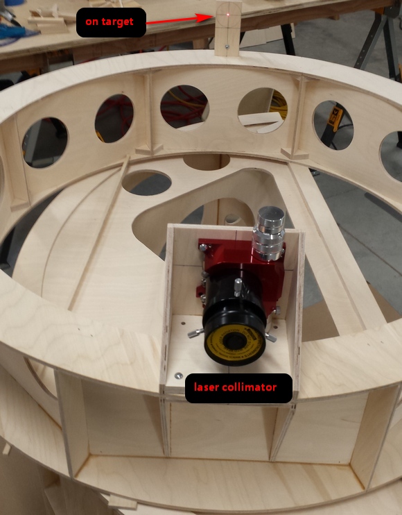
An optimization: letting the coma corrector intrude into the light beam a small amount
Pierre Lemay's three inch focuser adapter and attachment assembly
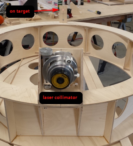
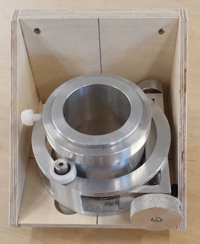
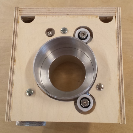
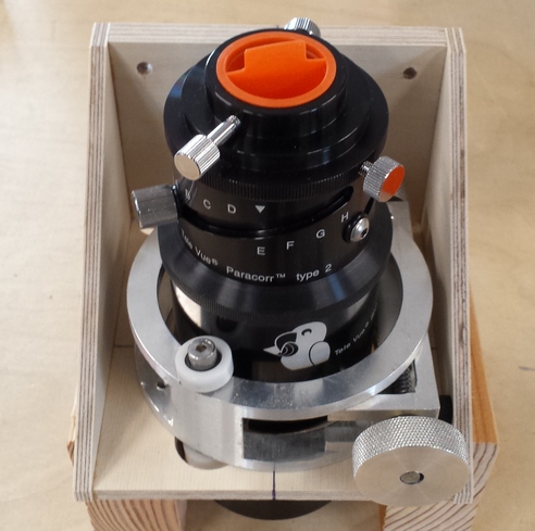
Step #25: build the diagonal holder and spider
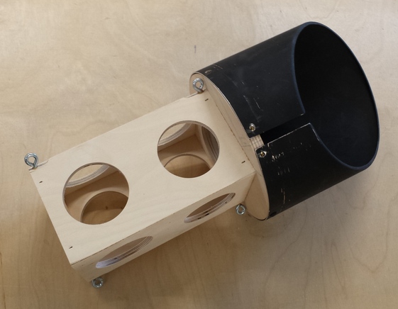
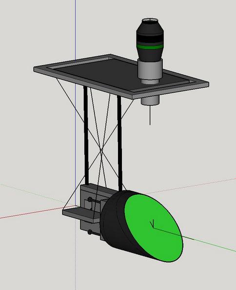
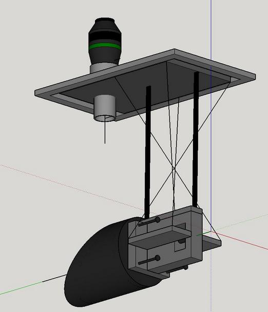
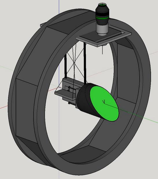
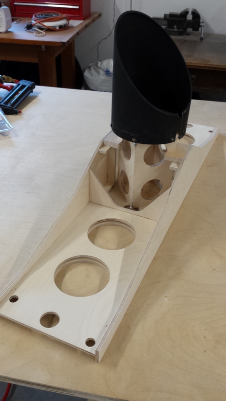
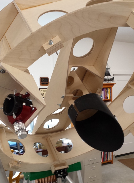
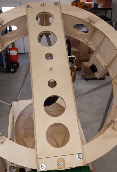
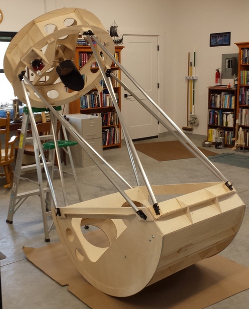
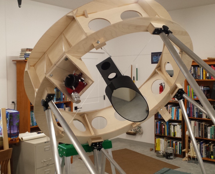
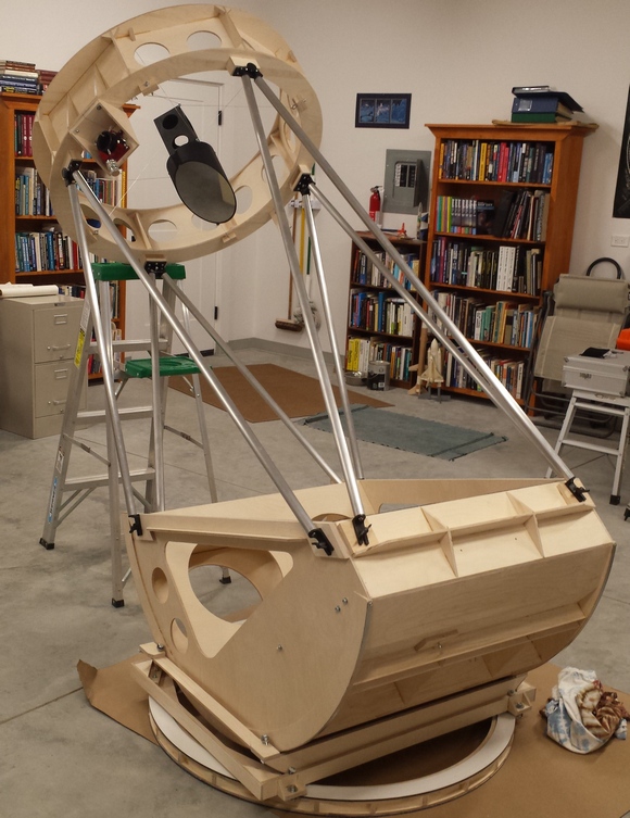
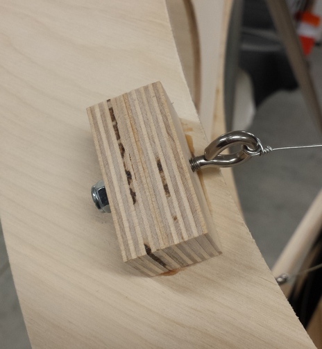
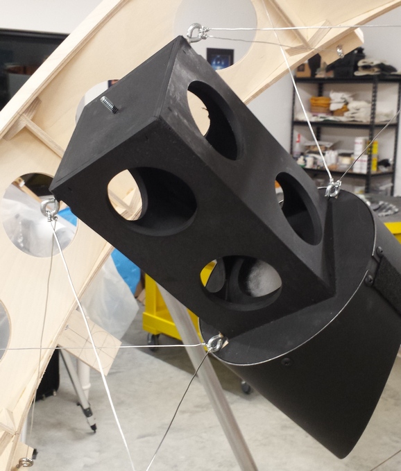
Step #26: select the finder
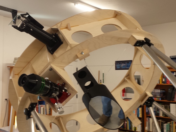
Step #27: assemble the trusses
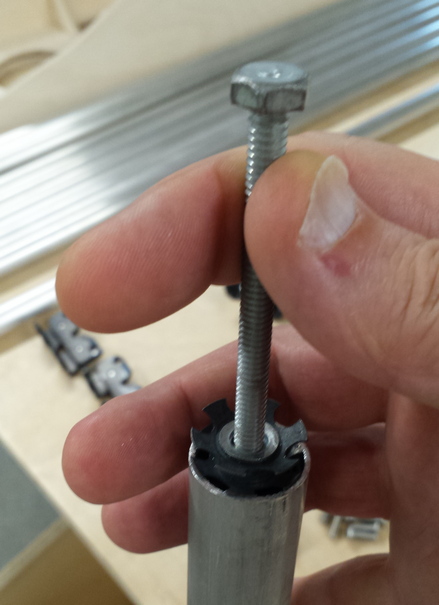
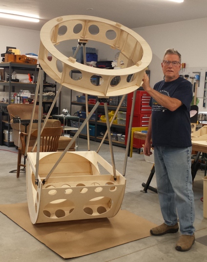
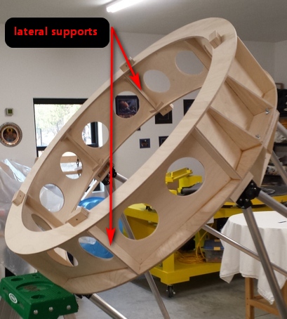
Step #28: three axes: why and how; the double flex rocker and flex base ring
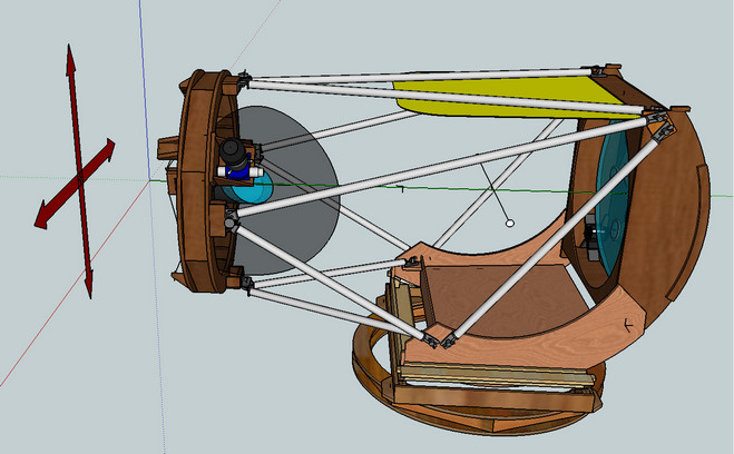
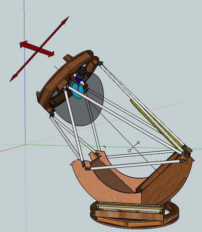
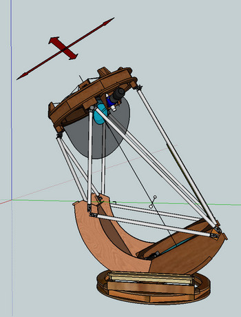
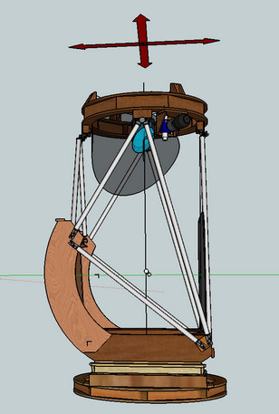
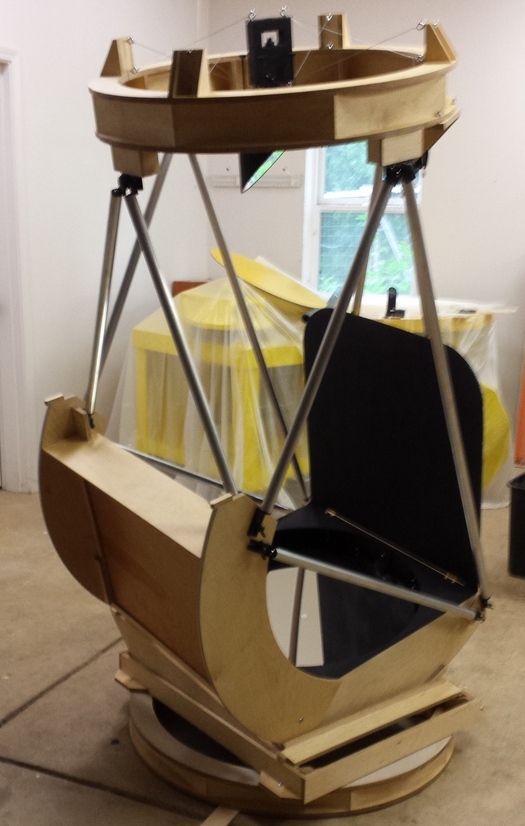
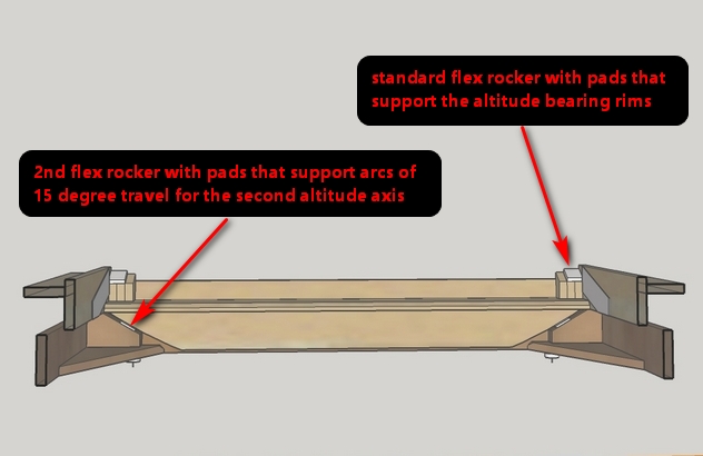
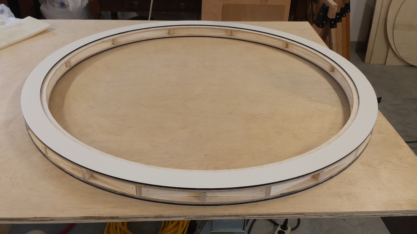
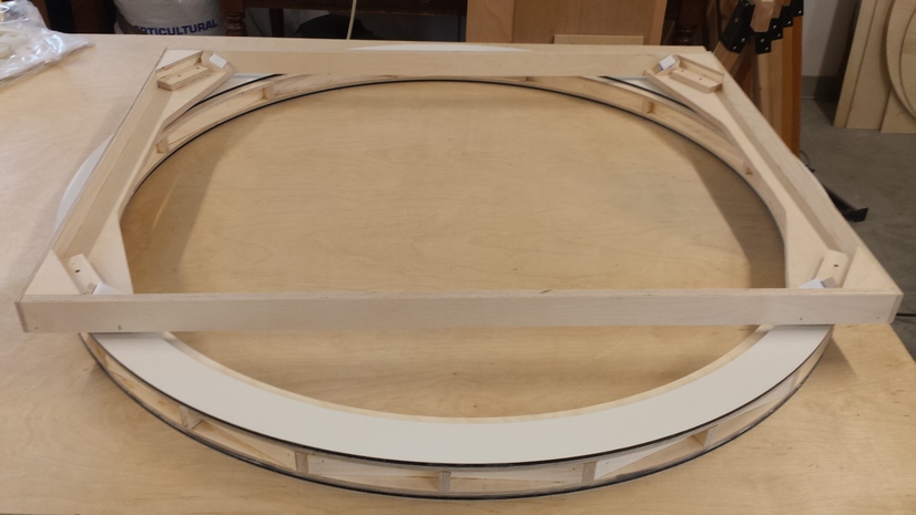
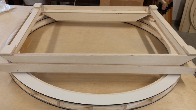
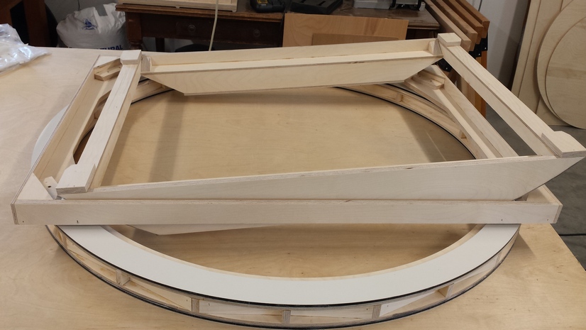
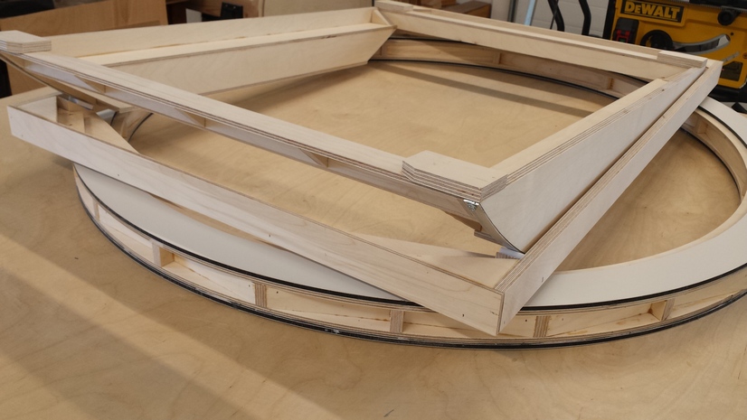
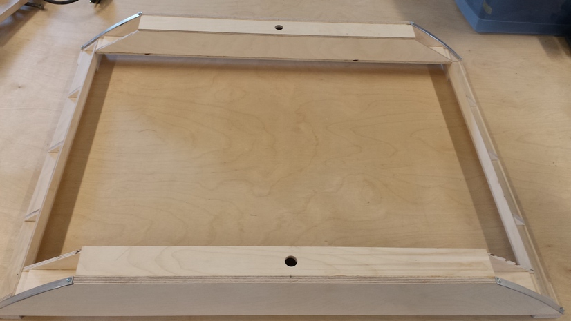
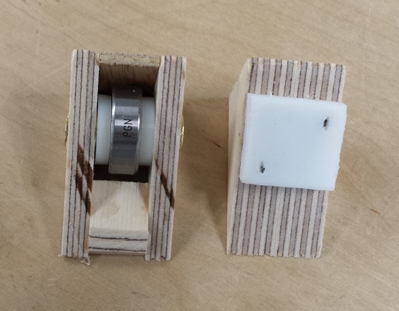
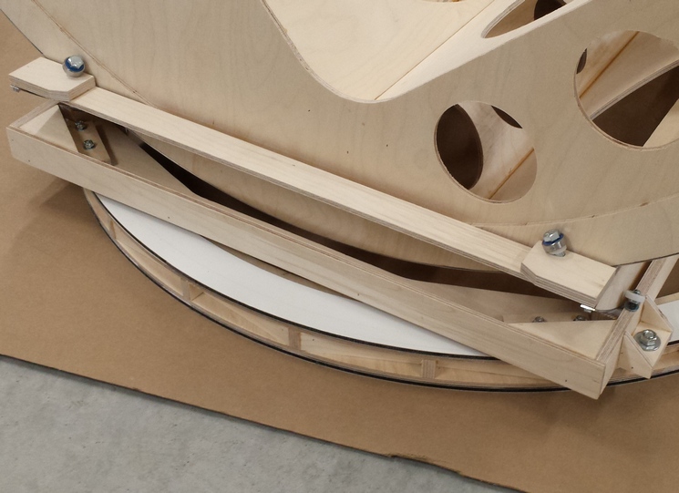
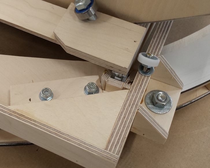
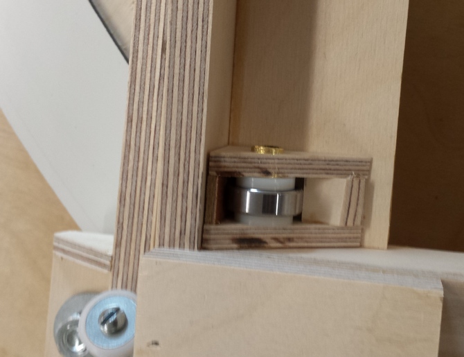
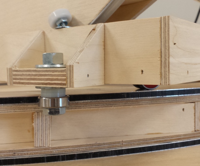
Step #29: friction of movement and bearing materials
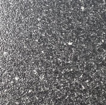
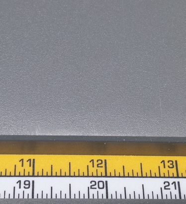
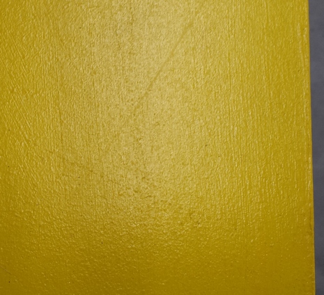
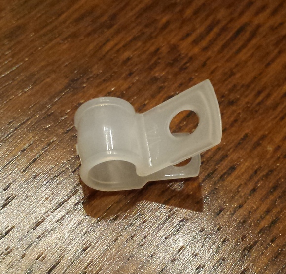
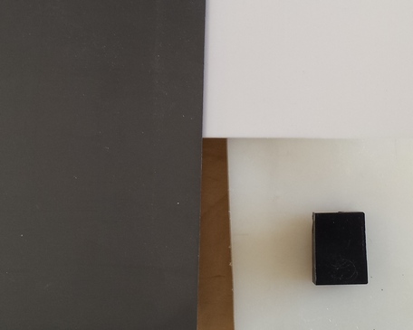
Step #30: counterweighting
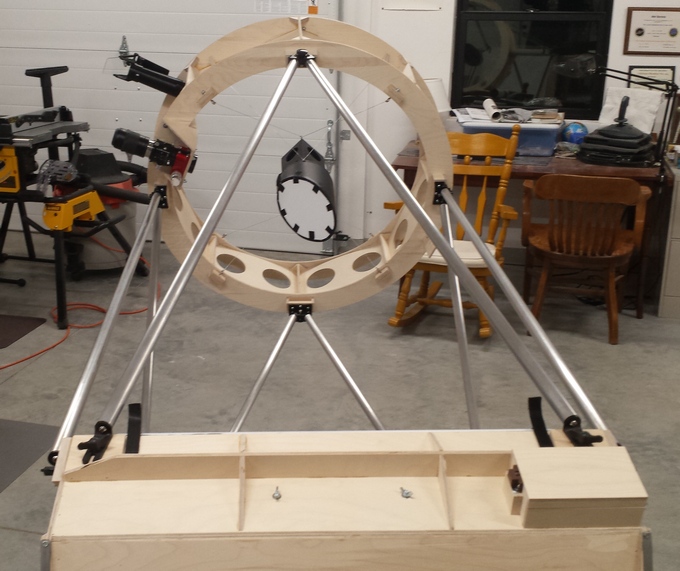
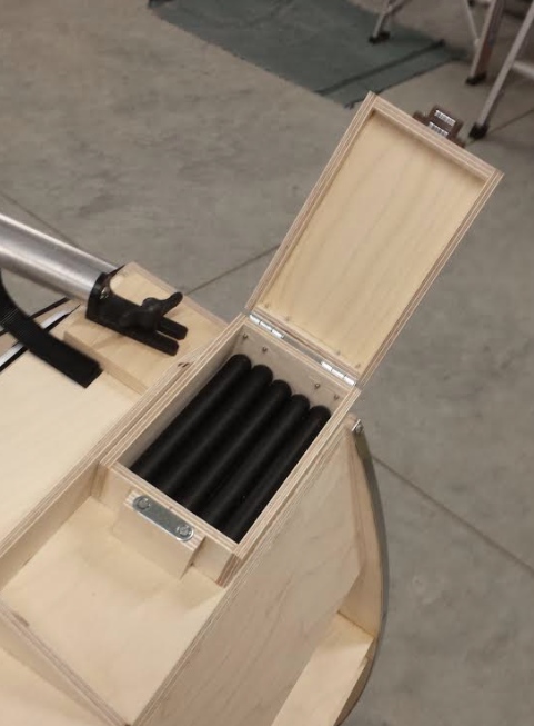
Step #31: the transport trolley
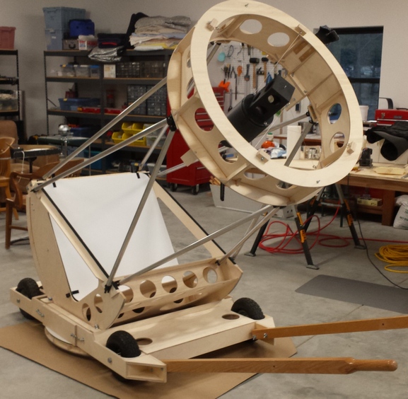
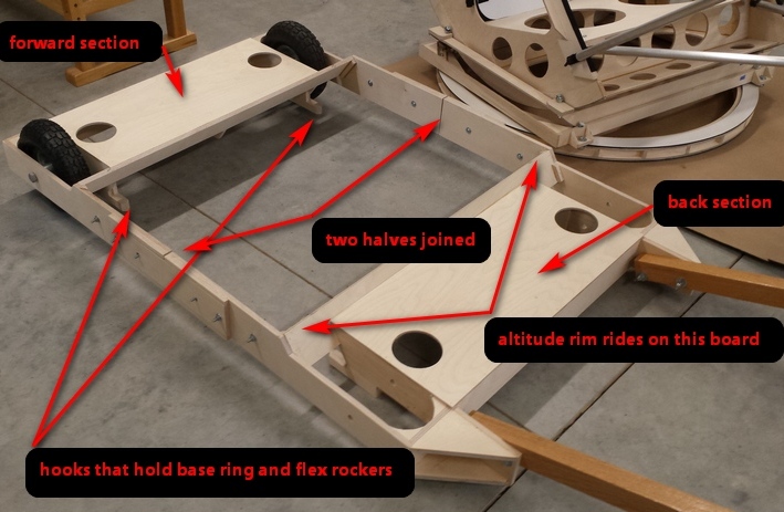
Step #32: baffling and shrouding
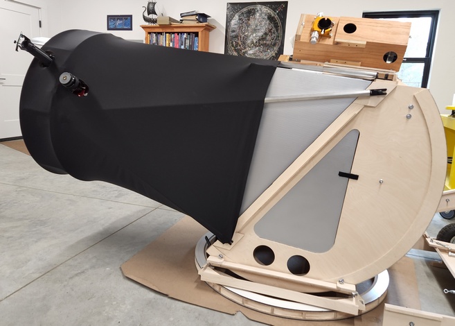
Step #33: aligning the optics
Step #34: verify the telescope
Step #35: silvering a mirror
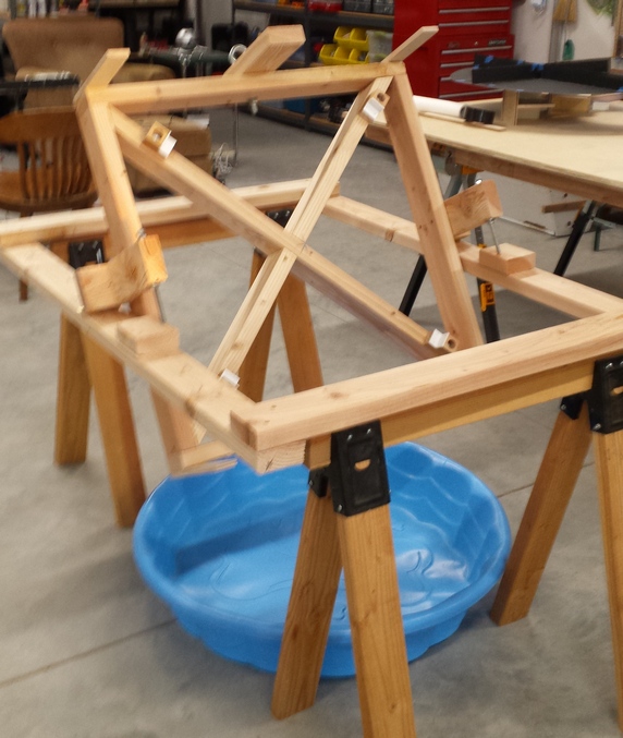
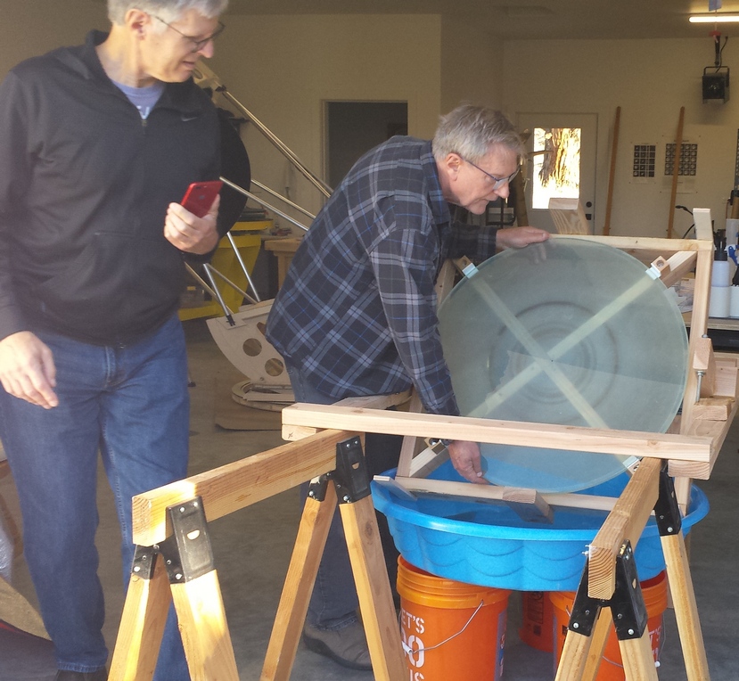
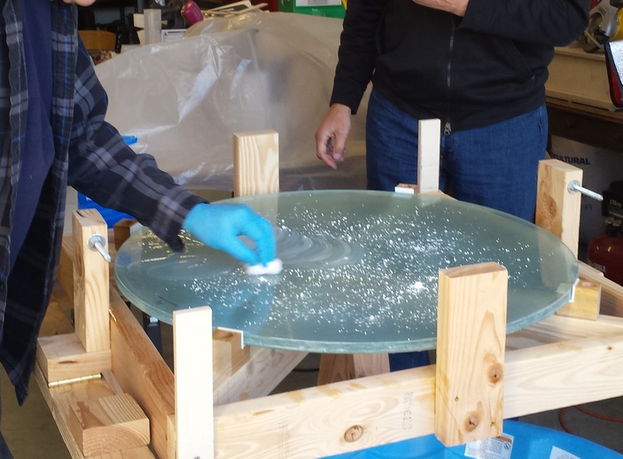
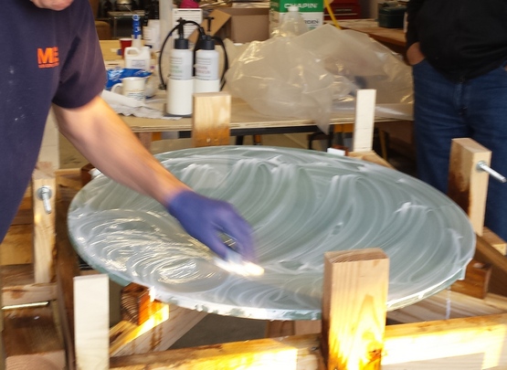
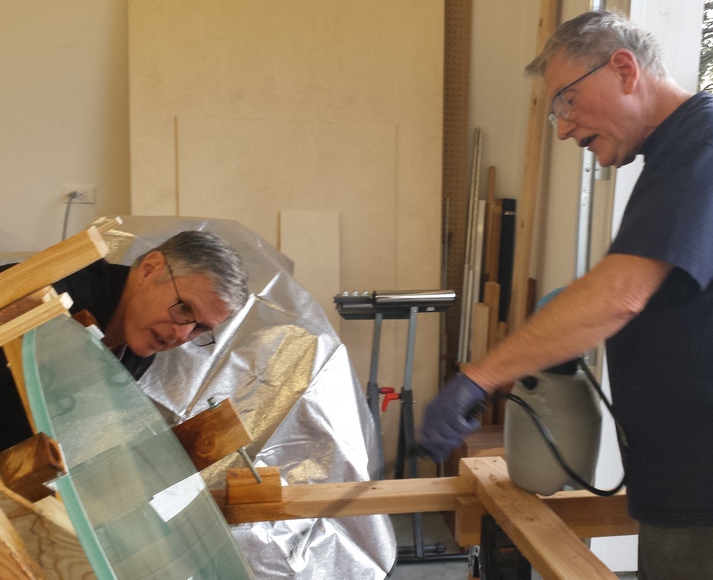
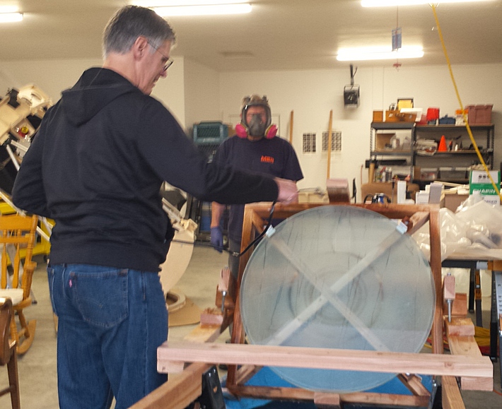
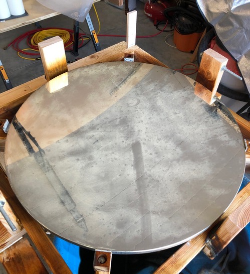
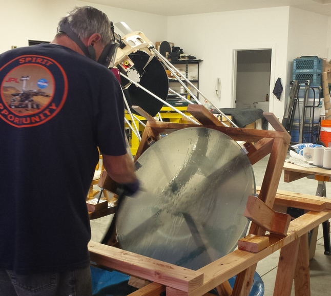
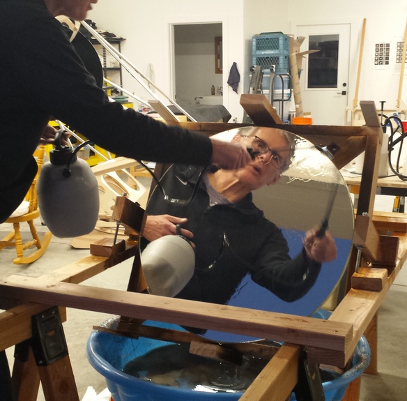
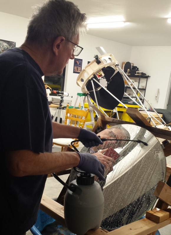
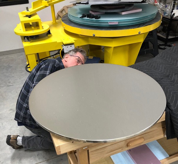
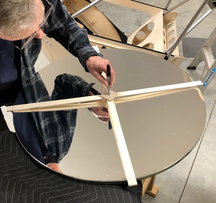
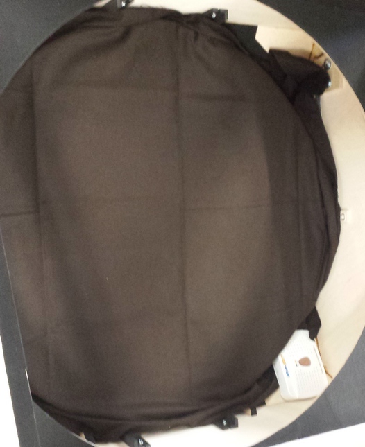
However, after four months the anti-tarnish cloth left a faint stain, visible with the flashlight test which did not impact observing. Twenty minutes of very gentle sweeping with dry cotton balls removed the stain; the mirror passes the flashlight test again. I am now using new technology anti-tarnish strips held above the mirror's face with plastic bolts and nuts.
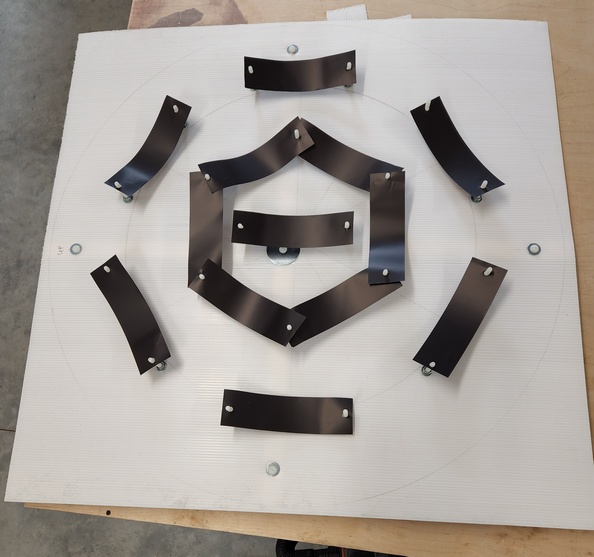
The flashlight test
Step #36: first light
Howard Banich's first light report as reported to the Oregon Scope Werks
Subsequent observing report
Observing report from spring 2022
Observing report from June 2022
Drawings
Step #37: the concept of etendue
Step #38: adjustments
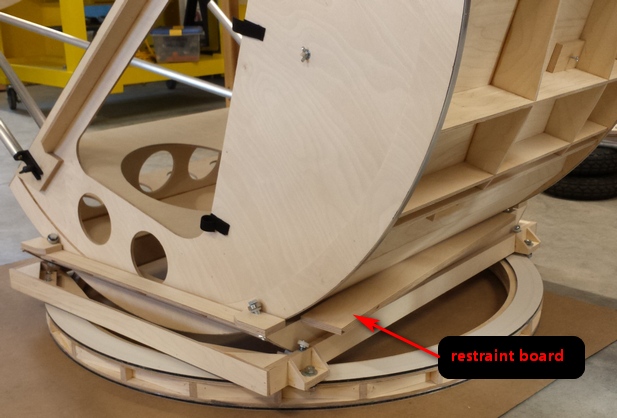
Thermal equilibrium, cooling and fans
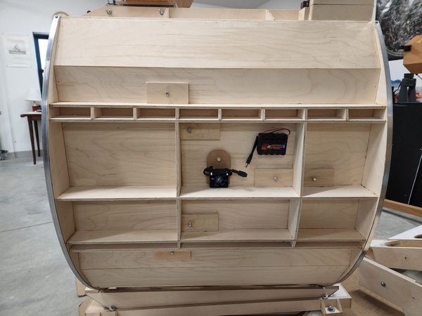

Step #39: enhancements
The 6 inch f2.8 scope for a 5 degree wide field perspective
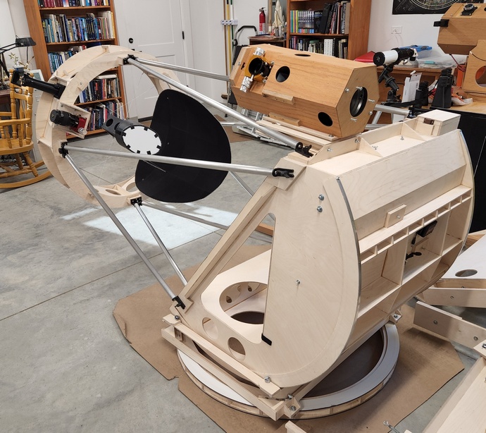
Widest lowest power fields using a non-magnifying coma corrector
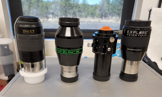
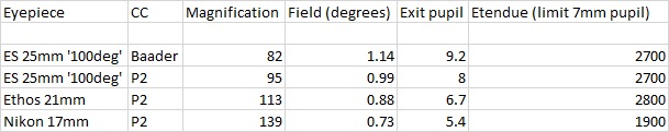
Weather and thermal protective cover
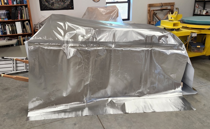
Off-axis masks
Night Vision (NV) device
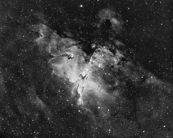
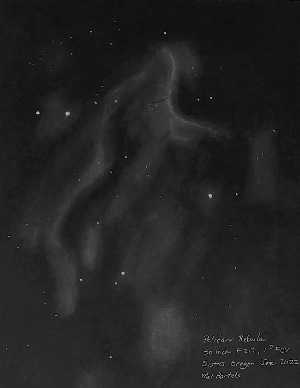
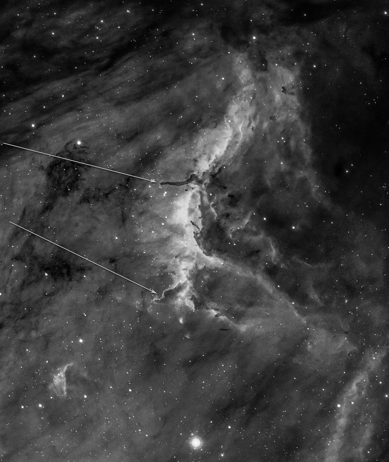
Spectroscopy
SkySolve camera based finder
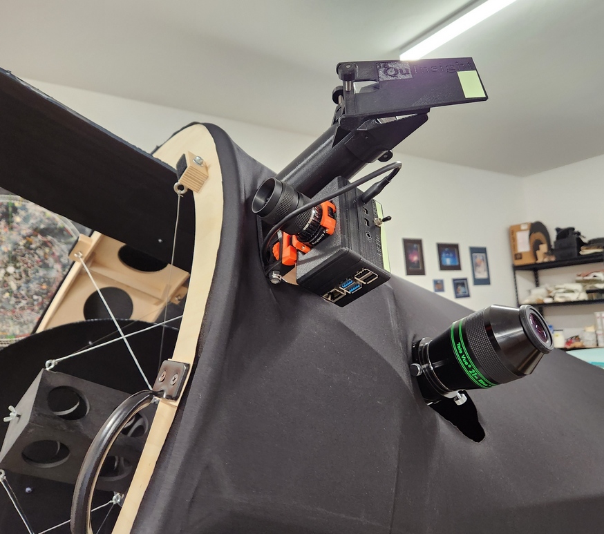
Changes made after the 2023 Oregon Star Party
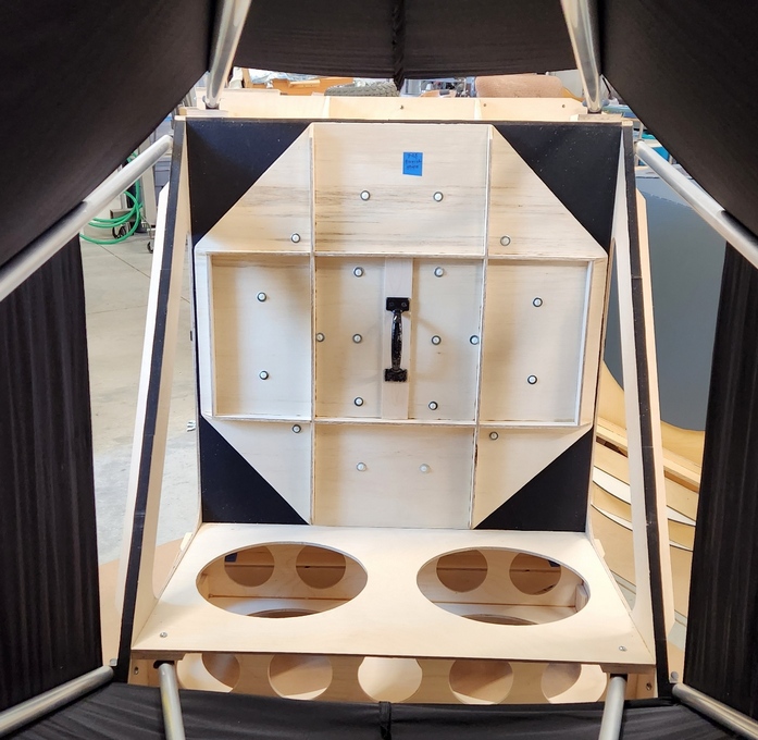
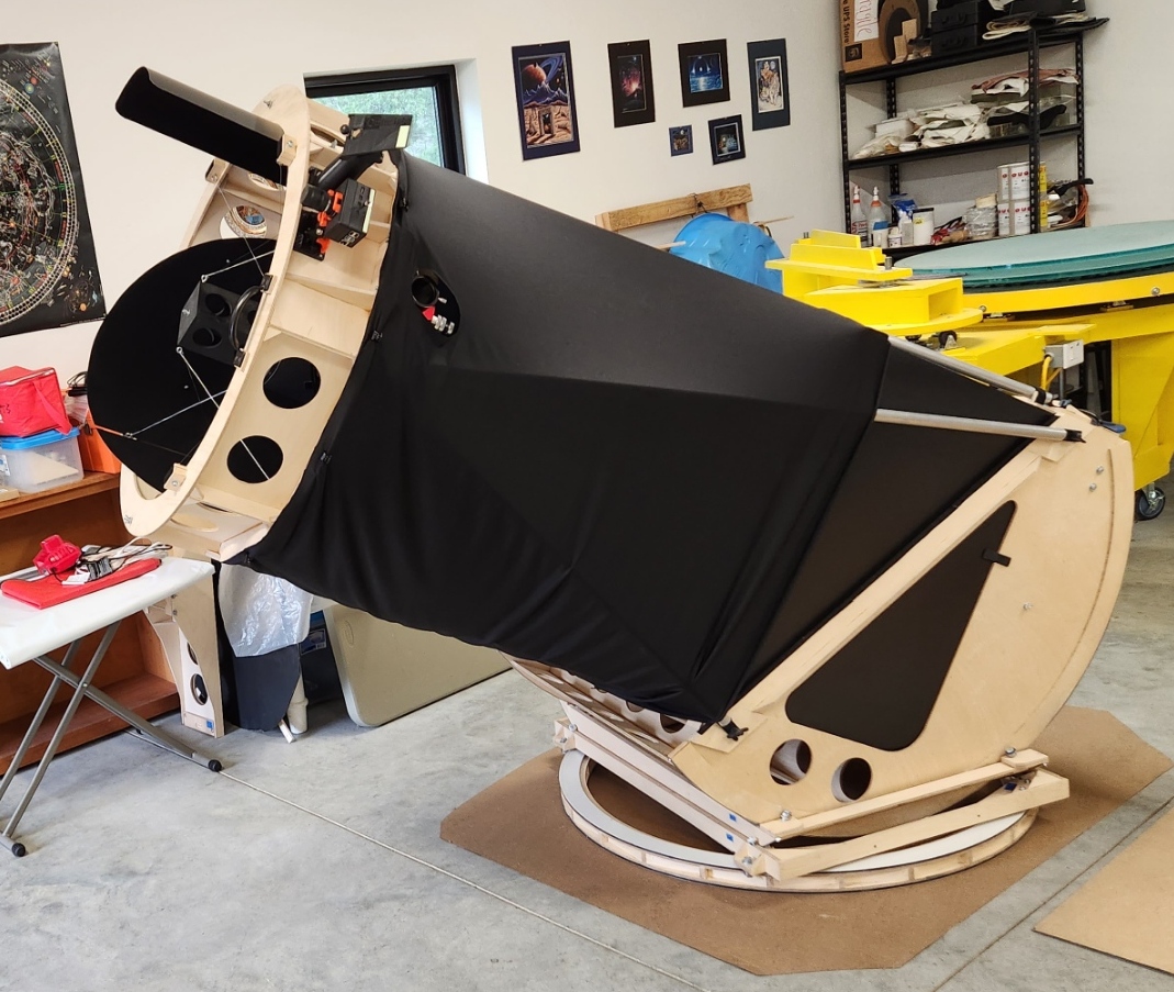
Front fans
Back pusher


Step #40: highlights

"The most memorable views for me at the Oregon Star Party were through Mel Bartel’s 30”. One of the motivations for me to attend OSP was to meet Mel and observe through his massive scope; he’s an exceptional mirror and telescope maker, pushing the boundaries of creating “fast” optics created from thin meniscus mirrors that are highly curved, which provide wider fields of view and a shorter overall telescope that doesn’t require a 16-foot orchard ladder to reach the eyepiece.
"There was understandably a small crowd of excited folks around Mel’s scope, and I waited patiently in line to view M13, the great Hercelus Globular Cluster, one of the crowning jewels of the northern hemisphere.
"The first thing that struck me was how sharp the stars looked; building a 30” f/2.7 primary mirror free of spherical aberration and astigmatism is extraordinarily difficult. The next thing I noticed was how overwhelmingly bright and colourful the stars in M13 looked. Everywhere I looked, nearly a million stars glittered in blue and yellow and gold and red. Mel told us to look for the integrated flux nebula (IFN) arcing around M13, and I could indeed see the whispy faint nebulousity extending around the globular. No photo of M13 that I’ve seen does this view justice - it needs to be experienced at the eyepiece.
"Next, Mel showed us the Ring Nebula, M57. Although the scope was at low power, I could immediately see that the outer portion of the Ring Nebula was “on fire” with a haunting red that went all the way around. To the layperson used to seeing pictures of these objects, seeing red in the Ring Nebula may sound like no big deal, but for me, having observed this object countless times before and never having seen any hint of colour, and seeing it so plainly here, the experience was transformative.
"The Andromeda Galaxy, M31, was also stunning. I could start to make out some of the textures in the two big dust lanes, looking 3-dimensional with an obvious tilt. The galaxy extended on and on as I nudged the scope. In these big Dobsonians, the views are very engaging, with so much detail that it’s easy to get lost in specific regions."
Goal: list the good, the bad and the ugly as lessons to learn for the next telescope
The good:
The bad:
The ugly:
What I will do differently next time: